
BUILT IN THE USA. READY FOR YOUR PROJECT.
Electrical Busway: New Equipment Replacement Planning
Replacing a busway connection is not simply a matter of matching the outside dimensions of an existing enclosure.
DIRECT FROM THE MANUFACTURER / NEW EQUIPMENT
THE MANUFACTURER’S PERSPECTIVE — 02
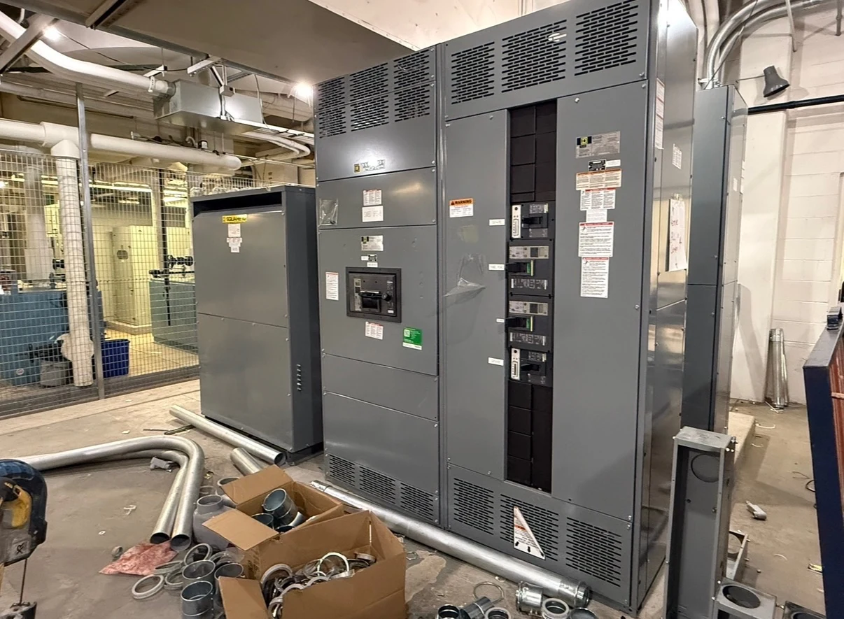
Replacing a busway connection is not simply a matter of matching the outside dimensions of an existing enclosure. The new distribution equipment must work with the electrical system, the route above or beside it, and the facility’s operating plan. Owners, electrical engineers, and contractors can reduce surprises by resolving those interfaces before ordering newly manufactured assemblies.
Start with the actual installation
Collect the current one-line diagram, busway and switchboard nameplates, feeder schedules, installation drawings, and records of subsequent changes. Mark which busway runs and tap-off loads will remain and which are in the project scope. An older drawing is a useful starting point, not proof that the field configuration still matches it.
Have qualified personnel document connection locations, phase and neutral arrangement, grounding and bonding provisions, conductor or bus material, and accessible dimensions. Photographs and measured elevations help identify interferences, but the design engineer must verify critical information through an appropriate site assessment. Record unknowns explicitly rather than treating them as compatible by default.
Prove the electrical interface
Give the manufacturer the system voltage, phase and wire configuration, required continuous current, available fault current, and upstream protective device information. The engineer should evaluate the new assembly and the retained busway together, including fault duty and protection coordination. A connection that fits mechanically may still be unsuitable for the system.
Load data matters as much as the nameplate: identify present demand, planned additions, nonlinear loads, and any neutral requirements. Compare a like-for-like interface with an engineered transition that accommodates changed capacity or layout. The transition may improve fit, but can add space, coordination, testing, and approval requirements; its feasibility must be confirmed for the specific equipment.
Resolve fit, movement, and support
Provide the busway manufacturer and model, joint or flange details, connection orientation, centerline elevations, and available working space. Neither bolt patterns nor phase positions should be assumed interchangeable across product families. Determine whether the connection can be made through a compatible approved interface or whether a different engineered arrangement is needed.
Coordinate the physical route with structural supports, building movement, expansion provisions, enclosure access, and nearby piping or ductwork. The design team should assign support loads and anchorage to the responsible structural and installation parties. Routing around an obstruction can affect the number of sections and joints, so an apparently small relocation may change procurement scope.
Compare new-equipment proposals fairly
Ask the direct manufacturer to identify what is included: the new distribution assembly, any proposed busway interface or transition, connection hardware, drawings, and factory checks. Confirm whether the busway sections themselves are included or supplied by another party. The installer’s field connections, structural work, permits, and site testing should have named owners.
Compare exceptions as carefully as base scope. Specify environmental conditions, applicable equipment standards, and any listing or inspection requirements. UL 891 may be relevant to an appropriate switchboard assembly; the project team must verify the proposed assembly’s listing and interface acceptability rather than assume it applies to every switchgear or busway configuration.
Build the owner-led outage plan
The owner should identify affected departments, critical loads, permitted outage windows, and any temporary-power needs before the equipment arrangement is frozen. A phased cutover can preserve service to some loads, but may require additional transition equipment and multiple interruptions. Have the engineer and contractor assess each phase for protection and source compatibility.
Document responsibilities for the shutdown sequence, approvals, communication, contingency plan, and return-to-service authorization. The contractor should account for field verification and unresolved dimensions in the schedule. All isolation, testing, connection, and energization work belongs to qualified personnel following the site’s safety procedures and applicable requirements; procurement documents are not operating instructions.
Tie submittals to delivery and turnover
Request a one-line, equipment elevations, connection details, foundation and loading information, and an interface drawing showing the busway boundary. Review these against field measurements before releasing fabrication. Record who resolves discrepancies, who approves revisions, and how changes affect component ordering, delivery dates, and the reserved outage window.
Before arrival, coordinate shipping sections, lifting access, receiving space, and protection from site conditions. Agree on project-specific factory documentation and field acceptance responsibilities, including checks at the busway-to-assembly interface. Turn over final drawings, relevant test records, manuals, and approved settings so the owner has a reliable basis for future operation and maintenance.
LET'S BUILD SOMETHING RELIABLE — 03
Ready to talk
switchgear?
Tell us about the new equipment your project needs. Include as much or as little detail as you have today.
(951) 403-5738CALL TO DISCUSS YOUR PROJECT