
BUILT IN THE USA. READY FOR YOUR PROJECT.
Switchgear Modernization
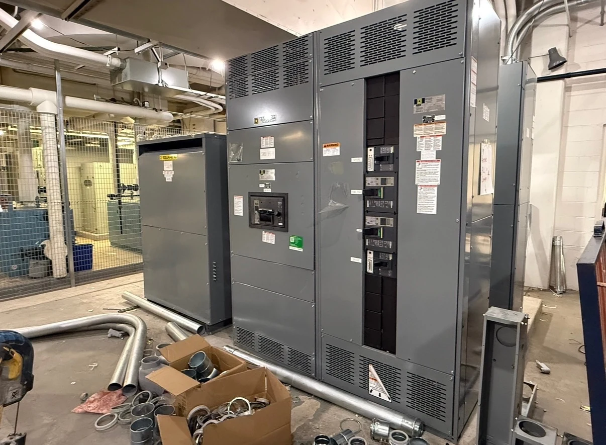
Modernizing a power distribution system is not simply a matter of matching an existing lineup’s footprint.
DIRECT FROM THE MANUFACTURER / NEW EQUIPMENT
THE MANUFACTURER’S PERSPECTIVE — 02
Modernizing a power distribution system is not simply a matter of matching an existing lineup’s footprint. A new assembly must work with the sources, feeders, protection and operating constraints that remain in the facility. For owners and specifying engineers, the early challenge is defining a workable transition as carefully as the end-state design, particularly when production or occupied spaces cannot be interrupted at once.
Establish what the facility actually has
Start with the latest available one-line diagram, load schedule, equipment drawings, protection studies and utility service information. Identify each source and feeder, its function and the loads it serves. Record nameplate information, conductor sizes and quantities, cable entry locations, known modifications and the space available for the new lineup.
Drawings and labels may not reflect changes made over the life of a facility. Arrange a site survey by qualified personnel under the owner’s safety procedures, and flag discrepancies for the design team rather than assuming the records are correct. Distinguish confirmed information from dimensions or ratings that still need verification before committing to fabrication.
Design for transition states as well as the final system
The engineer should identify normal and alternate sources, transformer characteristics, grounding arrangements and the intended relationship between mains, ties and feeders. A staged project can temporarily create different source configurations from the finished design. Available fault current, assembly withstand and protective-device interrupting duty need review for each relevant operating condition, not just the final one-line.
Document protection and coordination objectives alongside practical limits. For example, a new feeder breaker must be assessed against the upstream device that remains in service; matching its nominal current alone does not establish selective coordination. Where controls or interlocks cross the replacement boundary, define signals, power supplies, failure behavior and responsibility for the required study and settings.
Resolve physical and electrical interfaces
A lineup that fits on a plan may still conflict with cable bending space, door swing, heat removal or required working access. Coordinate the equipment footprint and height with the electrical room, foundation, delivery path and installation clearances. Specify top or bottom cable entry, terminal locations, conductor material and the number of conductors per phase and neutral.
If existing feeders must reach different termination points, the project team should evaluate extensions or other engineered connections, available space and who supplies the associated materials. Busway flanges, control cables, grounding connections and existing metering also need interface drawings. The design should not assume that a direct physical connection is acceptable without electrical and mechanical review.
Make the outage strategy part of the scope
Owners can rank loads by acceptable interruption, identify operating windows and coordinate affected occupants, process teams and the utility where applicable. The engineer and installation contractor can then compare a single cutover with sectional replacement. Phasing may reduce interruption to selected loads, but it adds temporary boundaries, additional engineering and potentially more field mobilizations.
If temporary power is contemplated, define its source capacity, connection interfaces, grounding and protection, and review the risk of unintended backfeed for each planned configuration. Include a contingency and return-to-service plan in the owner-led outage package. Switching, isolation and verification are responsibilities for qualified personnel following approved site procedures, not an equipment purchasing shortcut.
Request a comparable manufacturing proposal
As a direct American manufacturer of new electrical distribution assemblies, we coordinate equipment scope for projects in San Antonio, South Texas and nationwide. Send the design basis, identified uncertainties, feeder and device schedule, environmental requirements, desired metering and control functions, and the proposed phasing plan. Ask for explicit assumptions and exclusions so alternatives can be evaluated on equivalent scope.
Define the submittals and acceptance criteria before ordering: proposed one-line, elevations, connection details, device information, factory inspection and test records, and operating documentation as applicable. If a switchboard design calls for UL 891, confirm the listing and its scope for the proposed assembly; that standard should not be assumed to cover every type of switchgear.
Coordinate approvals, delivery and handoff
Schedule the site survey, design decisions and drawing review before the intended outage. Component availability, unresolved interfaces, approval revisions, fabrication and agreed testing can all affect the sequence. Coordinate shipping splits, dimensions, weights and lifting provisions with the receiving and rigging teams, and allow time for field installation and any required inspection.
Assign responsibility for foundations, field connections, protective settings, commissioning tests and final records in writing. The installation contractor and qualified test personnel work to the approved design and site safety rules; the owner controls the outage and authorization to return the system to service. Reconcile design changes and test results in the turnover package so the next operating team has a reliable baseline.
LET'S BUILD SOMETHING RELIABLE — 03
Ready to talk
switchgear?
Tell us about the new equipment your project needs. Include as much or as little detail as you have today.
(951) 403-5738CALL TO DISCUSS YOUR PROJECT