
BUILT IN THE USA. READY FOR YOUR PROJECT.
Automatic Transfer Switches: New Equipment Replacement Planning
Replacing an automatic transfer switch is more than matching a cabinet and ampere value.
DIRECT FROM THE MANUFACTURER / NEW EQUIPMENT
THE MANUFACTURER’S PERSPECTIVE — 02
Replacing an automatic transfer switch is more than matching a cabinet and ampere value. The new assembly must connect reliably to the normal source, alternate source and served loads while fitting a real outage plan. Owners, electrical engineers and contractors can reduce procurement risk by documenting those interfaces before requesting a newly manufactured assembly.
Start with the actual installation
Collect the latest one-line diagram, load schedule, equipment nameplates and available control drawings. Have a qualified professional confirm discrepancies and document field changes. Identify which loads the switch serves, whether an upstream disconnect is provided for each source, and whether life-safety or other essential loads impose special requirements on the design.
Record the normal and alternate source characteristics, system voltage, phase and wire configuration, continuous load and expected growth. The engineer should establish available fault current at the proposed location for each source and the protective devices involved. An old nameplate is useful evidence, but it does not establish that the original arrangement remains suitable.
Choose a transfer arrangement for the loads
An open-transition transfer separates the sources during a transfer; a delayed-transition arrangement adds an intentional pause where appropriate for the load. Closed transition can momentarily parallel sources and requires compatible equipment, protection and any applicable source-owner approval. Compare these approaches against permissible interruption, motor behavior and utility or generator constraints, rather than assuming the existing sequence is best.
Determine whether the neutral should be switched or solid as part of the engineer's grounding and bonding design. The decision depends on source configuration and the separately derived system assessment. Confirm the number of poles and the arrangement of grounding conductors; a seemingly minor change in neutral treatment can affect protection and the wider system.
Match protection and control interfaces
Specify the transfer switch's withstand and closing rating for the available fault duty and the particular upstream protective-device arrangements and clearing times, as applicable. Continuous current capacity alone is not a fault-duty assessment. Ask for the proposed rating documentation and any device or timing limitations so the engineer can check coordination against the short-circuit study.
List generator start contacts, source-available signals, remote inhibit commands, alarms and building-management points. Define control power, contact types, communication protocol and what the controller should indicate if a source or signal is lost. The generator supplier and controls contractor should agree on each wiring boundary and functional responsibility before drawings are approved.
Make the physical fit measurable
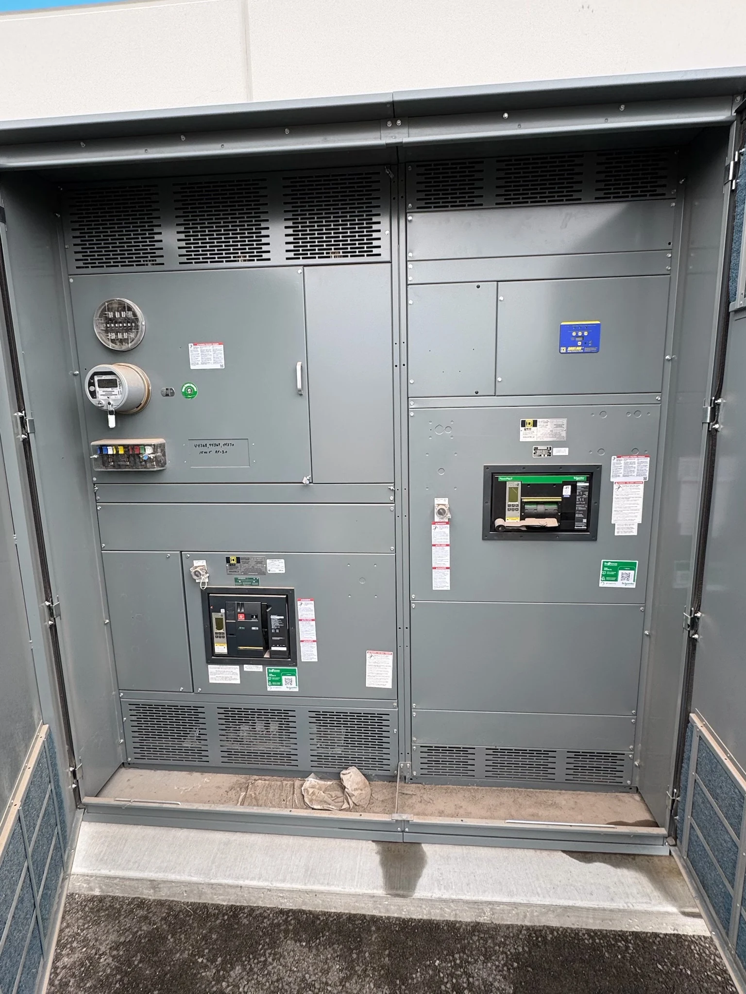
Provide photographs and dimensioned site information showing the installation route, equipment footprint, door swing and available working space. Note conduit locations, entry direction, conductor quantities and sizes, and termination constraints for both sources and the load. The contractor and engineer must verify required clearances and whether existing conductors can reach the new terminals.
Choose indoor or outdoor construction for the actual exposure, and describe moisture, temperature, ventilation and access expectations. A compact enclosure may ease delivery but restrict bending space or future service access. If existing conduit locations cannot align, include the necessary field adaptation in the project scope rather than assuming a direct fit.
Build the outage plan around dependencies
The owner should lead an outage plan with the electrical contractor, engineer, facility operators and affected occupants. Identify impacted loads, allowable interruption windows, permits and source-owner coordination. Where continuity is required, assess temporary power capacity, connection points and protection as a separate engineered scope, including its removal and a contingency if work cannot proceed.
The plan should assign isolation, installation, testing, restoration and authorization responsibilities, with a clear decision point for postponement or rollback. Only qualified personnel should perform electrical work under the site's safety procedures, including appropriate lockout and verification. Schedule around approvals and site constraints; a factory delivery date by itself does not establish an executable shutdown window.
Compare proposals and define handover
For a direct-manufacturer quotation, provide the source and load data, sequence of operation, site dimensions and proposed scope boundaries. Ask for a one-line, enclosure layout, terminal and control diagrams, ratings, exceptions and applicable listing information. Verify the listing for the particular transfer equipment and intended application; UL 1008 may be relevant to transfer switches.
Agree on review milestones, component availability assumptions, factory functional test scope and who witnesses or receives test results. Distinguish factory checks from site commissioning with the actual generator and load. At turnover, request final drawings, manuals, settings and test records, while the owner coordinates qualified field personnel and required acceptance with the relevant authorities.
LET'S BUILD SOMETHING RELIABLE — 03
Ready to talk
switchgear?
Tell us about the new equipment your project needs. Include as much or as little detail as you have today.
(951) 403-5738CALL TO DISCUSS YOUR PROJECT