
BUILT IN THE USA. READY FOR YOUR PROJECT.
Electrical Busway: One-Line and Feeder Planning
A busway can distribute power along a building route while keeping feeder connections organized at the source assembly.
DIRECT FROM THE MANUFACTURER / NEW EQUIPMENT
THE MANUFACTURER’S PERSPECTIVE — 02
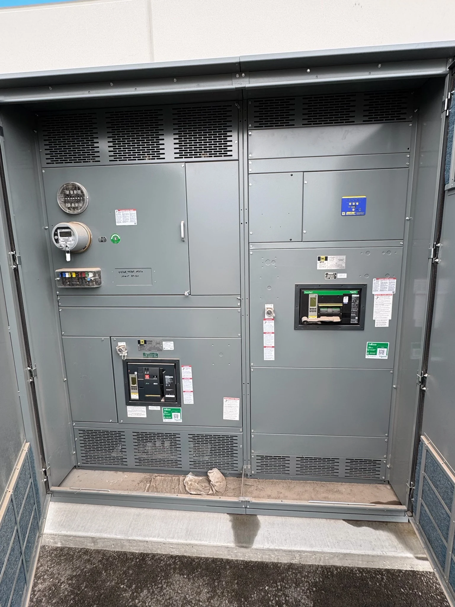
A busway can distribute power along a building route while keeping feeder connections organized at the source assembly. Its success depends on more than drawing a heavy line between two symbols. Engineers, contractors and owners need to agree on source conditions, downstream loads, physical interfaces and future changes before purchasing the new distribution equipment and associated busway.
Read the route from its source
Start the one-line at the supplying transformer, switchboard or switchgear and identify the device protecting the busway. Show system voltage, phase and wire arrangement, grounding configuration, available fault current and any alternate source or tie that can affect the busway. The engineer should distinguish normal operating configurations from other permitted source combinations.
Mark the busway's starting point, major direction changes and end, then label each planned feeder destination. A riser serving several floors may need different tap locations from a horizontal run supplying production equipment. A one-line shows electrical relationships, not a complete installation route, so pair it with coordinated floor plans.
Turn destinations into a feeder schedule
For each destination, identify the connected equipment, expected demand, operating duty and required number of phases and conductors. Include motor starting, nonlinear loads and any large intermittent loads when relevant. The electrical engineer can use those details to check capacity and voltage drop along the actual proposed route rather than assuming every tap carries the same load.
Distinguish a feeder busway run from a plug-in arrangement with tap-off positions. Plug-in capability can make later load relocation easier, but tap units, access and protective devices must fit the particular busway system. Record tap locations and individual ratings, and confirm whether each destination needs a neutral or equipment-grounding path.
Coordinate protection with busway duty
Continuous current, voltage class and short-circuit performance are separate checks. Provide the manufacturer's engineering team with available fault-current information at the busway source, study assumptions and the upstream protective device characteristics. Verify that the busway, connection equipment and tap-off devices are suitable for the calculated duty and the protection scheme, including applicable time limitations.
The coordination study should consider the source device and downstream tap protection across the relevant fault range. A larger upstream device may support expansion but can change protection and coordination choices. Do not assume that matching ampere numbers establishes compatibility or selective operation; the project engineer must review the actual equipment and study results.
Resolve the assembly-to-busway interface
Indicate whether the busway connects through a direct assembly interface or a cable transition, and identify who supplies each transition component. Exchange drawings showing termination orientation, phase sequence, neutral and grounding connections, mounting surfaces and allowable alignment tolerances. Busway and assembly suppliers should confirm that the proposed connection is mechanically and electrically compatible.
A direct connection may avoid a separate cable transition, but it can require tighter dimensional coordination and may affect how the equipment is shipped or installed. A cable transition can provide routing flexibility while adding termination space and field labor. Confirm support responsibilities, structural movement, enclosure conditions and required working access before finalizing either approach.
Plan growth without assuming free capacity
Show proposed future taps and their estimated loads separately from present feeders. A spare tap position is not the same as spare electrical capacity: the source, protective devices, busway and neutral must all be reviewed against the combined future operating scenario. Reserve physical access as well as capacity, especially where ceilings or other trades constrain the route.
Compare the cost and footprint of an initially larger system with a staged approach. Future expansion may require additional tap units, a changed protection study or a new section, depending on the selected system and approved design. Ask which options can be added later and what engineering and installation constraints apply before ordering.
Make the quote and handoff actionable
Send the direct manufacturer the current one-line, feeder schedule, preliminary route, source data, enclosure environment and project specification. Request a clear scope for the new distribution assembly, busway, tap units, supports, transitions and field connections; identify any items furnished by others. Confirm applicable equipment standards and any project-specific listing requirements instead of assuming a common listing covers every component.
Ask for coordinated submittal drawings, equipment ratings, interface details, installation documentation and agreed inspection or test records. Schedule design review and approval before releasing dimensions or long-lead components, and coordinate delivery and site access with the contractor. Qualified electrical professionals must perform installation, testing and energization under the project safety plan and applicable requirements.
LET'S BUILD SOMETHING RELIABLE — 03
Ready to talk
switchgear?
Tell us about the new equipment your project needs. Include as much or as little detail as you have today.
(951) 403-5738CALL TO DISCUSS YOUR PROJECT