
BUILT IN THE USA. READY FOR YOUR PROJECT.
Low-Voltage Switchgear: Protection and Coordination
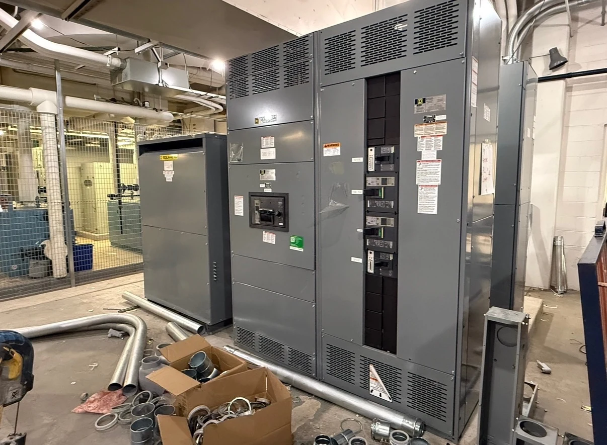
Low-voltage power circuit breaker switchgear does more than distribute power: its protective devices must respond to faults without unnecessarily interrupting healthy parts of a facility.
DIRECT FROM THE MANUFACTURER / NEW EQUIPMENT
THE MANUFACTURER’S PERSPECTIVE — 02
Low-voltage power circuit breaker switchgear does more than distribute power: its protective devices must respond to faults without unnecessarily interrupting healthy parts of a facility. For engineers, contractors and owners purchasing a new lineup, that outcome depends on source data, device selection and a coordination study—not simply on choosing breakers with the largest numbers.
Begin with the protection boundary
Provide the manufacturer with a current one-line showing utility service, transformers, generators, ties, mains and outgoing feeders. Include nominal system voltage, phase and wire configuration, grounding method, load schedules and the intended normal and alternate operating states. Identify critical loads and the circuits that should remain available when a downstream fault occurs.
Mark the boundary between the new assembly and equipment furnished by others. The study engineer needs the upstream protective device characteristics and downstream breaker or fuse information, not just the new lineup schedule. Where utility settings or transformer details are unavailable, identify the responsible party and obtain them before protection choices are finalized.
Evaluate fault duty at each location
Available fault current depends on the sources and impedance between those sources and the fault. Request utility contribution data, transformer ratings and impedances, conductor information and generator characteristics. The study should address relevant switching configurations, including conditions that produce the highest duty and lower-current conditions that can affect protective response.
The engineer compares calculated duty with the proposed circuit breakers and complete assembly under their applicable rating conditions. Interrupting capability, short-time withstand and peak or closing duty are different checks; continuous-current capacity alone does not establish fault suitability. Verify the actual ratings and any permissible combinations for the specific design rather than assuming that an upstream device makes every component acceptable.
Decide where selectivity matters
Selective coordination aims to isolate a fault with the protective device closest to it while upstream devices remain closed. The study engineer compares device characteristics across the applicable fault-current range and time intervals, including upstream and downstream equipment. Time-current curves are useful, but high-current behavior and manufacturer coordination tables or test data may also be needed.
Coordination can be limited by available trip functions, instantaneous behavior, device tolerances and the fault levels at different buses. Specify the circuits and operating conditions for which coordination is required, and ask the engineer to document exceptions. Delaying an upstream trip may improve selectivity but can increase equipment duty or arc-flash incident energy; those consequences must be evaluated together.
Match breaker functions to the study
Power circuit breaker trip units can offer different combinations of long-time, short-time, instantaneous and ground-fault functions. The specification should describe required functions and adjustment ranges while allowing the engineer to confirm the selected devices against the study. A more flexible trip unit may help resolve coordination conflicts, but it can add cost and configuration work.
Discuss fixed versus drawout construction where the project permits a choice. Drawout provisions can support planned maintenance and replacement of a compatible breaker, but add space and mechanical complexity. Confirm the assembly design, interlocks, breaker compatibility and access requirements; a drawout feature does not replace site-specific electrical safety procedures.
Coordinate sensing and source interfaces
Ground-fault protection requires agreement on the grounding arrangement, sensing scheme and neutral connections. Share transformer and generator grounding details, any switched-neutral arrangement and proposed sensor locations with the study engineer. Device settings and coordination with downstream protection depend on the complete system, so a generic settings schedule is not a substitute for analysis.
For multiple sources, define tie operation, interlocks, control power, trip signals and indications at each interface. A generator may contribute fault current differently from a utility source, affecting both sensitivity and timing. If remote monitoring or control is required, include the communications protocol, point list and responsibility for integrating and testing those signals.
Turn study requirements into a purchase scope
Request a proposal that identifies breaker types, protective functions, assembly ratings, applicable standards, drawings, exceptions and the assumed fault-duty information. State whether the manufacturer or an independent engineer supplies the short-circuit, coordination and arc-flash studies, and who approves final settings. Confirm project-specific listing requirements and availability rather than treating a product label as proof of every design requirement.
Set review milestones for preliminary studies, equipment submittals and final device data; late changes to sources or breakers can require revised drawings and analysis. Define factory inspection and functional-test scope, witness needs and records. Qualified personnel should perform field testing and commissioning under approved procedures, with the owner and engineer authorizing settings and energization.
LET'S BUILD SOMETHING RELIABLE — 03
Ready to talk
switchgear?
Tell us about the new equipment your project needs. Include as much or as little detail as you have today.
(951) 403-5738CALL TO DISCUSS YOUR PROJECT