
BUILT IN THE USA. READY FOR YOUR PROJECT.
15 kV Switchgear: Protection and Fault-Duty Review
A 15 kV system application calls for more than a voltage label on a switchgear proposal.
DIRECT FROM THE MANUFACTURER / NEW EQUIPMENT
THE MANUFACTURER’S PERSPECTIVE — 02
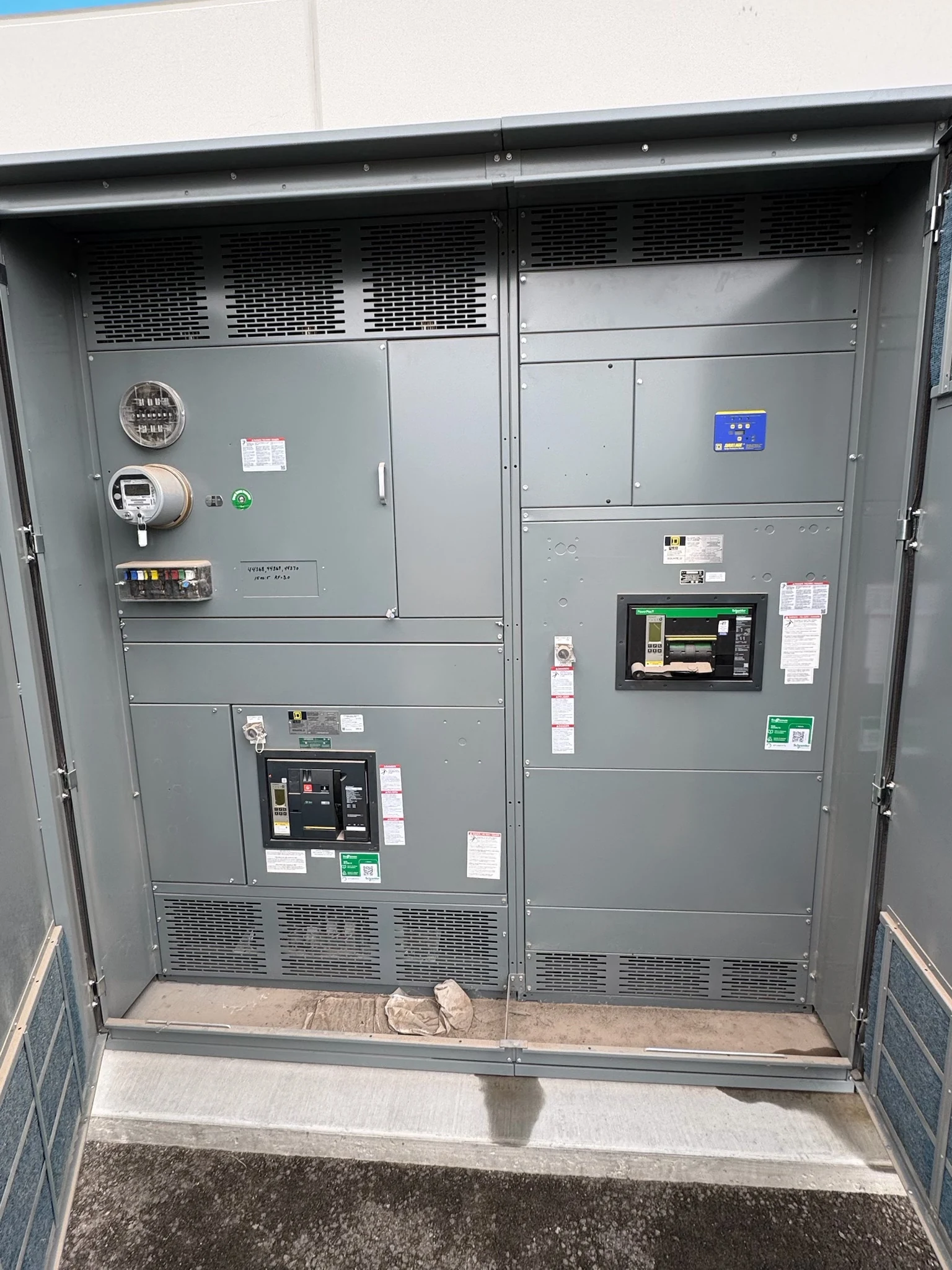
A 15 kV system application calls for more than a voltage label on a switchgear proposal. Engineers must match insulation, protective devices and fault-duty capability to the actual power system and operating scenarios. Owners and contractors can make the purchasing process more reliable by providing study data early and separating manufacturer equipment scope from protection-study and field commissioning responsibilities.
Establish the voltage and insulation basis
The one-line should identify nominal system voltage, grounding method, source arrangements and connected transformers. The engineer must confirm that the equipment maximum voltage and each primary device are suitable for the system, including expected operating conditions. A nominal voltage alone does not establish every insulation or switching requirement.
Ask for the applicable insulation withstand levels, including lightning impulse requirements, in the project specification. Environmental conditions such as altitude and contamination can affect the insulation design or its application. Confirm the equipment type, applicable standards and project-specific verification with the manufacturer; a 15 kV application does not mean every proposed product is available or appropriate for it.
Develop the fault-duty cases
Request current utility short-circuit information at the defined point of connection and document source impedance assumptions. The study should account for transformers, cable impedances, generators and motor contributions where applicable. Compare normal and alternate source configurations, including any permitted tie-closed or parallel operating state; the largest duty may not occur in the usual configuration.
Available fault current is not the same as a device rating. The engineer compares calculated duty with the proposed breaker interrupting capability and with assembly momentary or peak and short-time withstand capabilities as applicable. Fault duration, asymmetry and the system X/R ratio matter to the comparison, not just the symmetrical current number on a drawing.
Coordinate clearing without overlooking sensitivity
Protective relays, breakers and upstream devices should be evaluated as a system. A coordination study compares their time-current characteristics over the relevant fault range, considering transformer and feeder protection as well as utility requirements. Selective clearing is a design objective, not an automatic property of two devices placed in series.
Minimum fault cases are important too: a relay must be sensitive enough to detect faults under weaker-source or distant-feeder conditions. Slower upstream settings can give downstream protection time to operate, but can also lengthen clearing time and affect incident energy. The responsible engineer should document those compromises and the operating conditions used for the study.
Specify the relay and control interfaces
Identify required phase and ground protection functions, current and voltage transformer ratios, accuracy and burdens, and the relay inputs needed for the selected scheme. Transformer performance during faults must support the protection design. Decide which signals cross equipment boundaries, such as upstream trip, breaker status, alarms and any transfer or interlock permissives.
Clarify whether trip and close power comes from a station battery, control transformer or another project source, and define the interface and monitoring responsibilities. Loss-of-control-power behavior and test requirements belong in the design review. The manufacturer can coordinate assembly wiring and device submittals with the engineer responsible for relay settings and system studies.
Make proposals comparable
Provide a current one-line, load and feeder schedule, source fault data, expected operating states and the required voltage, continuous current and short-circuit design criteria. Include cable entry, metering, enclosure environment and spare ways where known. Identify unresolved utility information so a quotation can distinguish firm requirements from assumptions requiring confirmation.
Request a proposed one-line, device schedule, ratings, relay and instrument-transformer details, control-power requirements and a clear list of exceptions. Compare not only the breakers but the complete assembly, its documented duty and the scope of testing and documentation. Verify applicable equipment listing or certification for the actual configuration rather than assuming a standard applies.
Plan review, testing and turnover
Agree on dates for utility data, study inputs, drawing review and release of long-lead components before setting the project schedule. Changes to sources, grounding or feeder lengths can alter fault duty and settings after a proposal is issued. Record revisions and approvals so the manufacturer and study engineer work from the same electrical basis.
Define factory inspection and functional-test scope, witness requirements and acceptance records in the order. At turnover, provide approved drawings, device information, test reports and the final settings package to the owner and commissioning team. Qualified personnel should perform field testing, energization and any subsequent electrical work under site procedures and applicable requirements.
LET'S BUILD SOMETHING RELIABLE — 03
Ready to talk
switchgear?
Tell us about the new equipment your project needs. Include as much or as little detail as you have today.
(951) 403-5738CALL TO DISCUSS YOUR PROJECT