
BUILT IN THE USA. READY FOR YOUR PROJECT.
3,200-Amp Switchgear: Layout and Connection Planning
A 3,200-ampere designation is a starting point for a power-distribution design, not a guarantee that a particular lineup or rating is available.
DIRECT FROM THE MANUFACTURER / NEW EQUIPMENT
THE MANUFACTURER’S PERSPECTIVE — 02
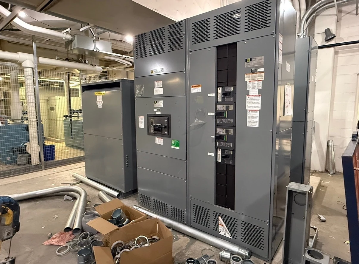
A 3,200-ampere designation is a starting point for a power-distribution design, not a guarantee that a particular lineup or rating is available. For a new assembly, the layout must accommodate the conductors, equipment access and building interfaces as well as the electrical duty. Early coordination gives engineers and contractors a workable basis for comparing proposals.
Define the lineup before drawing the room
Provide the manufacturer with a current one-line diagram showing each source, main device, tie, feeder and intended future connection. Identify system voltage, phase and wire arrangement, available fault current, grounding scheme and expected loads. The engineer must verify the continuous-current and short-circuit ratings of the complete proposed assembly, not just the main device.
A 3,200-ampere class can imply substantial connections, but the number of sections and actual footprint depend on device selection, bus arrangement and termination provisions. A compact elevation may reduce floor area while leaving less room for field wiring or future circuits. Ask for engineering review of availability, environmental conditions and the proposed ratings before treating a preliminary size as fixed.
Plan every conductor termination
For each incoming and outgoing circuit, identify the conductor material, size, quantity per phase, insulation and entry direction. Include neutral and grounding conductors, and describe any anticipated parallel runs. The designer can then check whether suitable terminals, cable bending space, support and physical separation fit the proposed compartment and selected assembly.
Top entry may simplify an overhead route but compete with ventilation or busway; bottom entry may fit an underfloor route but place demands on the slab and conduit layout. Ask the manufacturer to show usable entry zones and termination details. The electrical designer and installer must verify conductor sizing, permitted connections and installation requirements for the actual equipment.
Protect access as the footprint develops
Compare the equipment elevation and plan with the electrical room, adjacent walls, structural columns, piping and doors. Show front, side or rear access actually required by the proposed construction. Working space and dedicated equipment space depend on the installation and applicable rules; the project engineer should establish them rather than relying on a generic dimension.
Maintenance access can change the apparent space savings of a compact lineup. Consider door swing, removable covers, breaker handling where applicable, and a clear path for future component work. Coordinate room ventilation and heat rejection with the mechanical designer so that other building systems do not occupy needed access or compromise the equipment environment.
Coordinate adjoining equipment and supports
Where a transformer, busway or other assembly connects directly, exchange interface drawings early. Confirm connection elevation, orientation, phase arrangement, neutral and ground provisions, attachment details and who supplies the transition. A busway connection also needs coordinated support and allowances for building movement; the switchgear enclosure should not be assumed to carry unreviewed external loads.
For cable-fed connections, show conduit stub-ups or overhead tray routes against the approved entry zones. Coordinate slab openings, housekeeping pad dimensions, anchorage and structural loads with the building team. A small change to a transformer location or a conduit bank can affect termination space, so track revisions on both sides of the interface.
Make shipping and field boundaries visible
A lineup that fits the finished room may not fit through the receiving route. Check delivery access, lift capacity, door openings, turns and floor loading against the proposed shipping dimensions and weights. If shipment in sections is needed, ask where the splits occur and what space and materials field assembly will require.
The quotation should identify the division of responsibility for unloading, rigging, setting, anchoring, inter-section connections, cables and installation testing. Request lifting information and manufacturer instructions with the approved drawings. Only qualified personnel should perform electrical work and testing under site safety procedures and applicable requirements; the owner coordinates access and any necessary outages.
Use submittals to control cost and schedule
Ask for a proposal that identifies equipment type, preliminary dimensions, connection assumptions, applicable ratings, exclusions and any space reserved for expansion. Compare alternatives on total installed scope, not enclosure size alone: additional field labor, routing changes or reduced service access can outweigh an apparent equipment saving. Confirm any required listing for the specific assembly and application.
Set a review sequence for shop drawings, interface approvals, release for fabrication and delivery planning. Final submittals should show elevations, floor plan, entry areas, terminal provisions, shipping splits and responsibilities for field connections. Component availability, design changes and review turnaround can affect timing, so resolve open interface questions before committing the installation schedule.
LET'S BUILD SOMETHING RELIABLE — 03
Ready to talk
switchgear?
Tell us about the new equipment your project needs. Include as much or as little detail as you have today.
(951) 403-5738CALL TO DISCUSS YOUR PROJECT