
BUILT IN THE USA. READY FOR YOUR PROJECT.
Oil and Gas Switchgear
Oil and gas facilities depend on power distribution that fits both the process and the location.
DIRECT FROM THE MANUFACTURER / NEW EQUIPMENT
THE MANUFACTURER’S PERSPECTIVE — 02
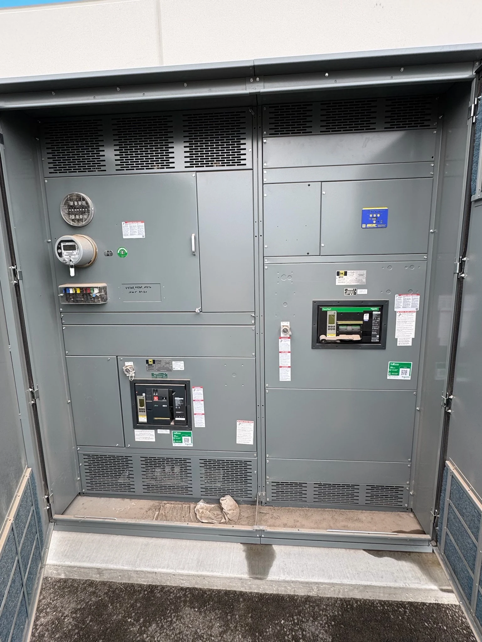
Oil and gas facilities depend on power distribution that fits both the process and the location. A compressor station, terminal or processing site may have large motor starts, variable operating states and equipment exposed to weather or corrosive contaminants. Owners and electrical engineers can procure a new switchgear assembly more effectively by defining those conditions before choosing a lineup or comparing quotations.
Start with the process load
Provide a current one-line diagram and a load schedule identifying sources, transformers, process motors, auxiliaries and intended feeder destinations. For each significant motor, include running demand, starting method, start frequency and any operating restrictions. Identify which loads may start together and which are required during abnormal or standby operation.
Motor starting can affect voltage at other loads and influence feeder and protective device selection. Variable-frequency drives introduce additional questions about harmonics, grounding and drive interfaces. The project engineer should evaluate these effects against the source and distribution system rather than assume that motor nameplate current alone establishes the assembly requirements.
Match protection to the system
Share the system voltage and configuration, available fault-current information at the equipment, transformer data and the expected operating states of each source. The engineer can use these inputs to evaluate assembly short-circuit capability, device interrupting duty and protection settings. Generator contribution and future system changes may also affect the study.
A coordination study helps compare upstream and downstream protective devices across the relevant fault range. Better selectivity can limit the extent of a process interruption, but it may compete with fault-clearing speed and other protection objectives. Agree on study ownership, relay interfaces and who will provide and apply approved settings; avoid treating coordination as an automatic outcome of buying a particular breaker.
Account for classified areas and exposure
Give the manufacturer the site area-classification drawings, installation location and applicable project standards. The responsible engineer must determine whether the proposed equipment and installation are suitable for that location, including cable entries and associated accessories. Locating equipment in a separately assessed electrical room may change the requirements, but a room is not automatically unclassified.
Describe ambient conditions, sunlight, dust, moisture, washdown and corrosive exposure, including potential salt or hydrogen sulfide where relevant. Enclosure materials, finishes, seals and ventilation need to be evaluated together: reducing contaminant entry can complicate heat removal. Define indoor or outdoor mounting, environmental controls and the available maintenance space before settling on the footprint.
Define controls and operating access
Provide a control narrative showing how the lineup interfaces with process control, emergency shutdown, fire and gas systems, and any alternate source. Document signal ownership, terminal points, control-power sources, alarms, permissives and the required response to lost power or communications. Safety functions and their independence belong in the owner’s engineering review, not in assumptions made during quoting.
For remote monitoring or control, agree on protocols, network boundaries, point lists and testing responsibilities with the site’s automation team. Also describe normal operator access and maintenance objectives. Compartments, device access and remote operation can influence layout and cost; the final arrangement must accommodate applicable working clearances and the facility’s safe-work procedures.
Compare complete manufacturing proposals
A direct American manufacturer of new distribution assemblies can help translate the design package into a project-specific proposal for work in San Antonio, South Texas or nationwide. Ask for a clear equipment boundary, preliminary arrangement, included devices, control wiring, enclosure provisions and deviations from the specification. Separate the base scope from optional features so bids can be compared on the same basis.
Specify the applicable equipment standard and any required listing for the proposed assembly. UL 891 may be relevant to an appropriate switchboard; it is not a blanket designation for all switchgear. Confirm the actual listing and its scope for the quoted configuration, and obtain approval for any proposed substitutions before they affect the design.
Plan submittals, delivery and turnover
Set review milestones for drawings, component selection, approved interfaces and release to fabrication. Component availability, design changes, customer approvals and the agreed testing scope all affect the schedule. Establish shipping dimensions, lifting and receiving constraints, cable entry, foundation details and responsibility for field assembly with the construction team early.
Define factory inspection and functional test scope, witness needs, acceptance criteria and test records in the purchase documents. At turnover, request drawings, equipment instructions, component information and the agreed test documentation. The owner should coordinate installation, field testing, settings verification and energization authorization with qualified personnel, the contractor and the site’s electrical safety procedures.
LET'S BUILD SOMETHING RELIABLE — 03
Ready to talk
switchgear?
Tell us about the new equipment your project needs. Include as much or as little detail as you have today.
(951) 403-5738CALL TO DISCUSS YOUR PROJECT