
BUILT IN THE USA. READY FOR YOUR PROJECT.
Neutral Bus Sizing
A neutral bus is more than an extra termination bar.
DIRECT FROM THE MANUFACTURER / NEW EQUIPMENT
THE MANUFACTURER’S PERSPECTIVE — 02
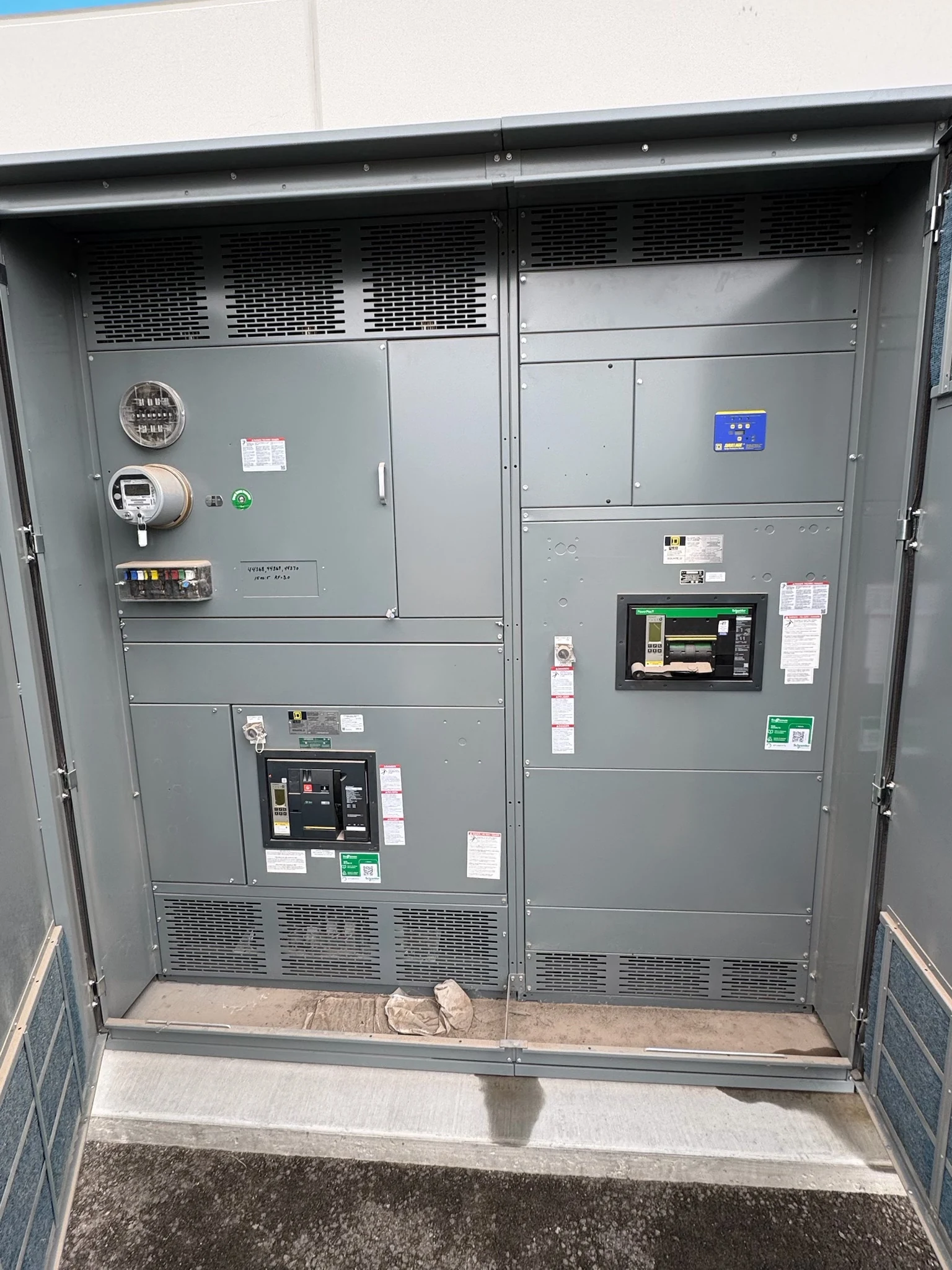
A neutral bus is more than an extra termination bar. Its continuous-current capacity, connections and physical arrangement must suit the actual loads and sources connected to a distribution assembly. Specifying engineers, contractors and owners can avoid costly redesign by identifying neutral current and termination needs before requesting a new switchboard or switchgear lineup.
Start with the neutral load, not the phase-bus label
For an ideal balanced three-phase system with linear loads, fundamental-frequency neutral currents cancel. Real facilities have changing single-phase loads and imperfect balance, so the neutral may carry current even when phase conductors appear similarly loaded. A neutral sized solely by copying or reducing the phase-bus rating can miss the actual duty.
Provide a one-line, voltage and phase-and-wire configuration, load schedule, demand assumptions and planned additions. Identify which loads need a neutral and whether their operating patterns coincide. The engineer should calculate neutral loading using applicable code requirements and project conditions rather than assuming that equipment nameplate currents simply add or cancel.
Account for nonlinear loads and harmonic current
Computers, LED drivers and other electronic power supplies can draw distorted current. In a three-phase four-wire system, third-harmonic and other triplen components from single-phase loads can add in the shared neutral rather than cancel like balanced fundamental components. The resulting heating concern depends on the actual load mix and waveform.
Where available, share a power-quality study or appropriately collected measurements, including harmonic content and operating conditions. Measurements are a snapshot, not a substitute for projected additions or changed usage. The designer can assess whether a full-size or larger neutral path is justified; no single oversizing percentage is appropriate for every installation.
Specify the entire neutral current path
A large main neutral bar alone does not establish the capacity of the whole assembly. Ask the manufacturer to review bus segments, joints, links and associated terminals together, including any connections across shipping sections. The proposed continuous-current capability must be supported by the assembly design and its applicable ratings, not just a conductor dimension.
Discuss ambient conditions, enclosure ventilation and expected loading because heat dissipation affects the design. A larger neutral path may increase material, enclosure space and cost; a reduced neutral may be acceptable only where the calculated load, applicable rules and assembly design permit it. Confirm short-circuit duty and bracing separately from continuous-current capacity.
Make conductor landing space part of the order
List incoming and outgoing neutral conductors by circuit, quantity, material and size, including parallel conductors where specified. Give the intended cable-entry direction and identify the party providing lugs. The manufacturer can evaluate terminal compatibility, conductor temperature limitations, bending space and access alongside the available neutral bus capacity.
A neutral bar with sufficient ampacity may still lack enough suitable landing positions. Spare terminals and space for future feeders can avoid a crowded layout, but they do not automatically establish spare electrical capacity. Review the termination schedule and arrangement drawings with the installer before releasing the design for production.
Coordinate source switching, bonding and protection
Normal and alternate sources can change the path taken by neutral current. Supply the generator and transfer-switch arrangement, including whether the neutral is switched, and identify separately derived sources where applicable. The engineer should coordinate those choices with the grounding and bonding design rather than treating the neutral as interchangeable with the equipment grounding bus.
Ground-fault sensing is another interface: sensor placement, neutral routing and bonding locations must work together for the specified protection scheme. Provide the protection one-line and control requirements for review. Qualified design and field personnel should resolve these interfaces under applicable codes, utility requirements and equipment instructions before commissioning.
Turn assumptions into reviewable deliverables
For a direct-manufacturer quotation, request a stated neutral rating and configuration, termination provisions, construction assumptions and any exceptions. Submittals should show the neutral bus arrangement, source and feeder interfaces, equipment ratings and relevant connection details. Confirm the applicable equipment standard and any project-specific listing, including its scope, rather than assuming a listing covers every configuration.
Schedule time for the design team and contractor to review those documents against the load study and site routing. Changes to nonlinear loads, conductor quantities or transfer arrangements can affect space and procurement after approval. Before energization, qualified personnel should perform the specified inspections and tests; retain approved drawings and records for the owner.
LET'S BUILD SOMETHING RELIABLE — 03
Ready to talk
switchgear?
Tell us about the new equipment your project needs. Include as much or as little detail as you have today.
(951) 403-5738CALL TO DISCUSS YOUR PROJECT