
BUILT IN THE USA. READY FOR YOUR PROJECT.
277/480V Switchgear: Layout and Connection Planning
A 277/480V distribution project needs more than a voltage on a one-line diagram.
DIRECT FROM THE MANUFACTURER / NEW EQUIPMENT
THE MANUFACTURER’S PERSPECTIVE — 02
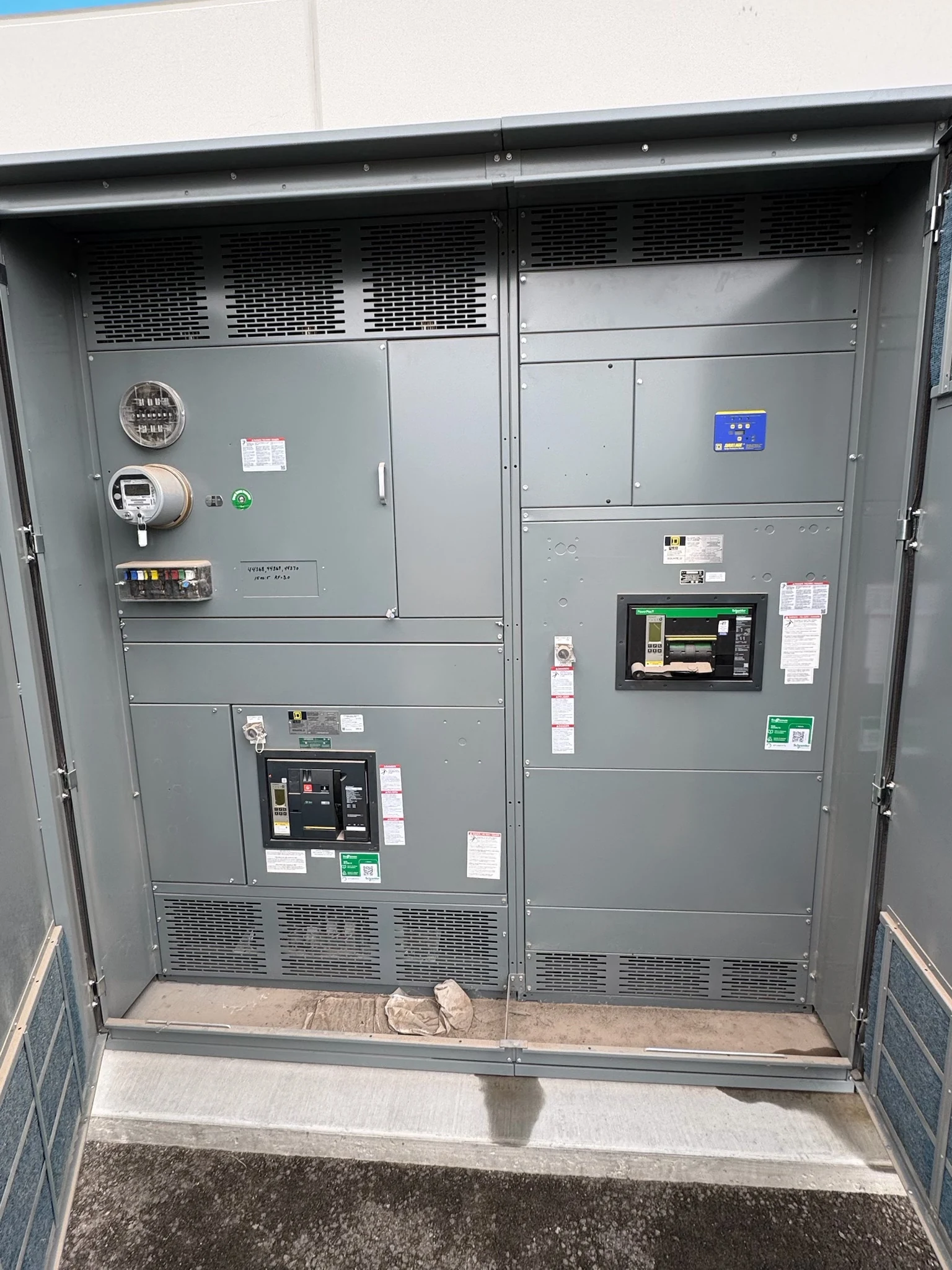
A 277/480V distribution project needs more than a voltage on a one-line diagram. The source configuration, conductor routes, protective devices and access needs all influence the shape and construction of a new assembly. Owners, engineers and electrical contractors can prevent costly layout changes by settling these interfaces before ordering equipment, then reviewing the manufacturer's drawings against the actual installation conditions.
Start with the system, not the footprint
In a typical 277/480V grounded-wye system, 480 volts is nominally measured phase to phase and 277 volts phase to neutral. Confirm the actual source, grounding arrangement, number of phases and wires, and intended loads rather than assuming every 480V system has the same neutral connection. Identify each incoming source and any planned tie or alternate supply.
The engineer should select an appropriate equipment voltage class and insulation system for the application, including the grounding arrangement and expected system conditions. Protective devices also need suitable voltage and interrupting ratings, while the complete assembly must be evaluated for its assigned fault duty. A nominal system designation alone does not establish compatibility or product availability.
Make space for the conductors
Provide the manufacturer with conductor material, size, number of parallel runs, insulation type and intended entry direction for each source and feeder. Large or multiple cables can drive the width of a termination compartment even when the breaker itself is compact. Top entry may simplify overhead routing; bottom entry may fit underground ducts but compete with the foundation and floor openings.
Review the proposed lug arrangement, termination quantities, wire-bending space and access for field connections against the actual conductor schedule. Confirm who supplies the lugs and whether they are compatible with the specified conductors and the assembly. A room plan that shows conduits entering the equipment outline, rather than just a single arrow, helps reveal clashes early.
Plan neutral, grounding and service interfaces
Where 277V line-to-neutral loads are served, give the engineer the neutral conductor and load information, including significant nonlinear loads. Neutral bus capacity, terminals and routing must be reviewed for that application; neither a reduced neutral nor an enlarged one should be assumed without analysis. Reserve physical connection space for the required neutral and equipment grounding conductors.
For service equipment, identify the utility's metering and incoming connection requirements as well as the project's grounding and bonding design. The engineer, utility and manufacturer must resolve the service boundary and required provisions before the layout is frozen. Generator, transfer equipment or busway interfaces likewise need defined connection points, phase arrangement and responsibilities.
Protect access around the lineup
A drawing should show more than the enclosure perimeter. Indicate required working space, door swing, removable covers, ventilation paths and any rear or side access the selected design needs. The project team must check applicable code, local requirements and manufacturer instructions for the actual equipment and installation, rather than relying on a generic clearance dimension.
Coordinate the electrical room with structural supports, sprinklers, piping, floor elevations and other trades. Front-access construction can be useful where the rear is constrained, but its suitability depends on the equipment design and the specific maintenance tasks. Allow a practical path for future device removal and cable work without assuming that every component can be serviced from the front.
Review drawings and the delivery boundary
Request a proposal that identifies the new assembly's configuration, voltage and current ratings, fault-duty basis, enclosure, devices, termination provisions and exceptions. Review elevations, one-line diagrams, connection details, anchor locations and shipping weights against the design documents. If a switchboard listing is specified, verify the applicable UL 891 listing and its project-specific scope; do not apply that assumption to every switchgear assembly.
Determine the shipping splits, receiving route, lifting provisions and field reassembly scope before accepting the dimensions. Sections that fit a truck may still be too large for a site doorway or lift route. The contractor and structural team should coordinate foundation openings, anchorage, tolerances and responsibility for interconnections between shipped sections.
Sequence approvals and qualified installation
Place utility data, fault-current information, conductor schedules and room constraints on the procurement schedule alongside the manufacturer's drawing review. Device availability, engineering revisions, fabrication and agreed testing can all affect the delivery plan. Record open decisions and approval dates; a late change in cable quantity or source arrangement can alter both the lineup and its interfaces.
Define the handoff: approved drawings and instructions, agreed inspection or test records, and final documentation should reach the installer and owner. The electrical contractor and other qualified personnel perform field work and commissioning under applicable codes, site safety procedures and manufacturer instructions. The owner coordinates any outage and energization authorization; delivery of an assembly is not permission to energize it.
LET'S BUILD SOMETHING RELIABLE — 03
Ready to talk
switchgear?
Tell us about the new equipment your project needs. Include as much or as little detail as you have today.
(951) 403-5738CALL TO DISCUSS YOUR PROJECT