
BUILT IN THE USA. READY FOR YOUR PROJECT.
600-Amp Switchgear: Protection and Fault-Duty Review
A 600-ampere designation describes a nominal continuous-current class, not the strength of a short circuit that the equipment can safely handle.
DIRECT FROM THE MANUFACTURER / NEW EQUIPMENT
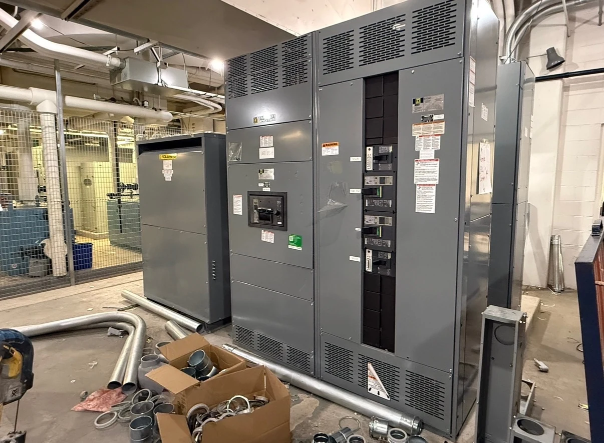
THE MANUFACTURER’S PERSPECTIVE — 02
A 600-ampere designation describes a nominal continuous-current class, not the strength of a short circuit that the equipment can safely handle. Owners, contractors and engineers buying a new distribution assembly need to establish both the expected load and the fault conditions at its intended location. Actual equipment configuration, ratings and availability require project-specific engineering review; a page title alone does not establish that a particular assembly is available.
Separate load capacity from fault duty
Continuous-current capacity concerns normal operation under specified conditions. Interrupting rating concerns a protective device's ability to interrupt a short circuit at its rated voltage and other stated conditions. Assembly short-circuit ratings address the equipment as a whole. These measures are related, but none can be inferred simply from the 600-ampere label.
Provide the design load schedule, system voltage, phase and wire arrangement, source configuration, and expected future additions. The engineer can then review the main device, bus and feeder ratings alongside ambient and enclosure conditions. A 600-ampere main-device request does not by itself establish the rating of every feeder or the suitability of the complete lineup.
Establish the available fault current
Request current utility source information for the service point and identify its assumptions and date. The study provider also needs transformer capacity and impedance, conductor lengths and sizes, and the intervening distribution arrangement. Motor contribution and other sources can affect the calculated duty at the assembly; a utility value at one point is not automatically the value at another.
Show normal, alternate and any permitted tie configurations on the one-line diagram. A generator, for example, may produce a different fault-current profile from the utility source. Ask the study provider to evaluate relevant maximum and minimum fault conditions and document assumptions, including the current basis and duration where they affect device or assembly selection.
Match device and assembly ratings
The design team should compare the calculated duty with the voltage and interrupting ratings of each proposed protective device and with the applicable short-circuit rating of the complete assembly. Where short-time withstand is specified, its duration matters: equipment must be evaluated against both the fault duty and the clearing time of the protective scheme.
Bus supports, connections and enclosure construction are part of the assembly evaluation, not just the breaker selection. If a proposal relies on a series combination, request documentation identifying the exact devices and conditions for its recognized rating, and confirm acceptability with the engineer and authority having jurisdiction. A higher-rated main alone does not establish downstream adequacy.
Define coordination and its limits
Coordination aims to isolate the affected portion of a system while preserving power to unaffected loads. Breaker trip functions or fuse characteristics must be considered with upstream and downstream devices. Give the study provider the actual device types, trip units or fuse classes, and upstream protective characteristics rather than relying on generic curve shapes.
Specify whether selective coordination is required and for which sources and fault-current ranges. Time-current curves help reveal overlaps, but coordination at high fault currents may also depend on manufacturer selectivity data and the exact device combination. An adjustable trip unit offers flexibility, while a simpler device may reduce complexity; either choice must fit the documented study.
Balance clearing time with operating needs
Delaying an upstream trip can improve selectivity with a downstream device, but longer fault clearing can increase incident energy and may affect equipment withstand requirements. The project engineer should examine coordination, short-circuit duty and arc-flash results together instead of treating maximum selectivity as the only objective. Applicable requirements and the facility's continuity priorities determine the acceptable balance.
Ground-fault protection, when required or specified, also needs a documented sensing and coordination scheme that accounts for the neutral and grounding arrangement. Alternate-source behavior and any source interlocks belong in that review. Qualified personnel must establish settings and perform testing under site safety procedures and manufacturer instructions; procurement literature is not an operating procedure.
Buy against a documented review package
When requesting a quote for a newly manufactured assembly directly from an American manufacturer serving San Antonio, South Texas and nationwide, include the one-line, load schedule, fault study or source data, device schedule, enclosure conditions and required standards. For a switchboard where UL 891 is applicable, ask for the proposed assembly's project-specific listing and scope to be confirmed.
Compare quotations for protection functions, assembly and device ratings, documented exceptions, drawings and test records. Assign responsibility for the system studies, final settings, field testing and acceptance to named project parties. Allow time for utility data, engineering submittal review, component confirmation and any revisions before release; a change in source or device can trigger a fresh duty and coordination review.
LET'S BUILD SOMETHING RELIABLE — 03
Ready to talk
switchgear?
Tell us about the new equipment your project needs. Include as much or as little detail as you have today.
(951) 403-5738CALL TO DISCUSS YOUR PROJECT