
BUILT IN THE USA. READY FOR YOUR PROJECT.
Electrical Switchboards
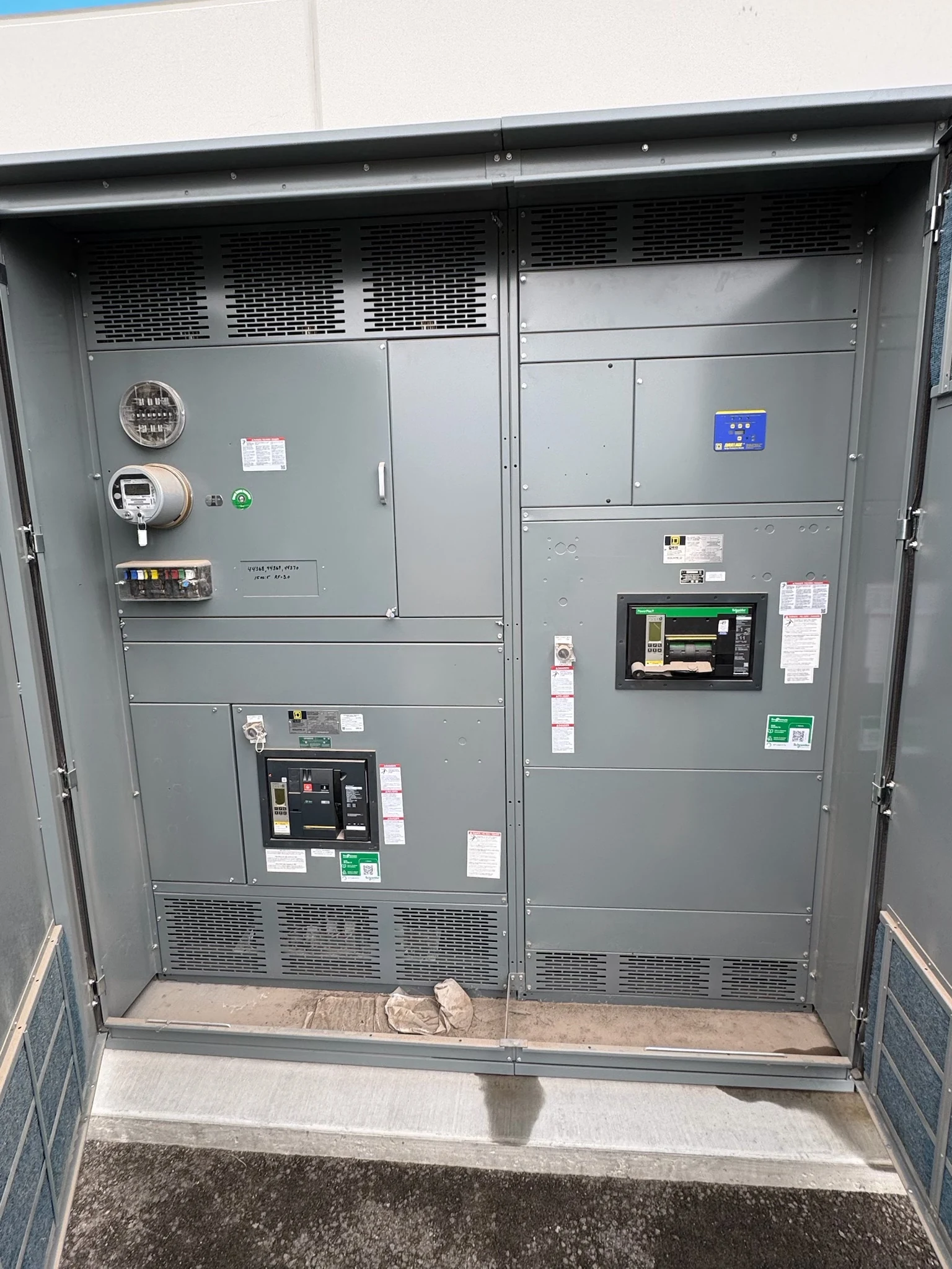
An electrical switchboard brings a building’s incoming power and outgoing feeders together in a coordinated low-voltage distribution assembly.
DIRECT FROM THE MANUFACTURER / NEW EQUIPMENT
THE MANUFACTURER’S PERSPECTIVE — 02
An electrical switchboard brings a building’s incoming power and outgoing feeders together in a coordinated low-voltage distribution assembly. For an engineer, the central question is whether its construction and protective devices fit the system; for an owner or contractor, installation access and project sequencing matter just as much. A direct manufacturer can develop a new assembly around documented requirements for projects in San Antonio, South Texas, and nationwide.
Define the switchboard’s role
A service switchboard receives power at the service entrance and distributes it to building loads. A downstream distribution switchboard instead receives a feeder from other equipment and divides it among additional circuits. Identify which role applies: utility metering, service disconnect provisions, grounding and local approval requirements may differ.
A switchboard is not automatically interchangeable with low-voltage power circuit breaker switchgear. The design team should compare the specified devices, construction, fault performance and maintainability rather than select solely on footprint. A more compact arrangement may suit a constrained electrical room, while a different equipment class may better support the owner’s maintenance philosophy.
Develop a useful one-line and load schedule
A quotation starts with a current one-line diagram showing each source, transformer, main device and feeder. Include system voltage, phase and wire arrangement, available short-circuit information, and the proposed continuous-current rating. Identify whether an alternate source, transfer equipment or a future tie changes the operating configuration.
List each feeder’s load, expected demand, protective device and conductor details, alongside anticipated future loads. Distinguish a spare equipped feeder from reserved physical space: either has implications for bus capacity, dimensions and cost. Nonlinear loads also warrant review of neutral current, metering and heat rather than an assumption that every conductor carries the same load.
Coordinate fault duty and protection
The engineer should obtain the available fault current at the proposed connection point and consider the sources that can contribute to it. The switchboard’s short-circuit rating, its bus and its protective devices must be suitable for the evaluated conditions. Breaker interrupting rating and assembly short-circuit rating describe different things and should not be treated as interchangeable.
Select feeder and main protection with the upstream and downstream devices in view. A coordination study can show where time-current characteristics overlap and whether the desired continuity is achievable across relevant fault levels. If a series-rated combination is proposed, verify the specific approved combination and its application; do not infer suitability from individual device labels alone.
Resolve physical and field interfaces
Provide room dimensions, equipment access paths and the intended top or bottom cable entry. Conductor quantity, size, material and termination arrangement affect lug selection, bending space and section width. Coordinate transformer or busway connections separately, including connection geometry and responsibility for any transition pieces.
The enclosure must suit indoor or outdoor exposure, temperature, moisture and ventilation conditions established for the project. Reserve working clearances and maintenance access under applicable requirements, not just space for the equipment outline. Shipping splits, lifting provisions, weights and anchorage details also need review before the contractor commits to the delivery route and foundation.
Specify metering, listing and documentation
Decide whether meters serve utility billing, owner monitoring or both. Utility requirements can govern meter compartments and instrument transformer interfaces, while an owner’s monitoring system may require additional measurements, communications and a defined point list. Confirm who furnishes each meter, current transformer and field connection before drawings are released.
UL 891 is relevant to appropriate low-voltage switchboard assemblies; confirm the required listing and its scope for the specific proposed assembly. Request a one-line, elevations, device schedule, connection details and documented exceptions in the submittal package. Agree on factory inspection or functional checks, acceptance criteria and records rather than assuming a particular test is included.
Coordinate purchasing and project timing
When comparing manufacturer proposals, align the feeder count, protection functions, enclosure, metering, listing and documentation before comparing commercial terms. Clarify who supplies field cables, foundations, protection settings and commissioning. State any domestic-component requirements in the purchase specification and verify actual sourcing and availability instead of assuming every part has the same origin.
Allow for drawing review, utility or authority approvals where applicable, component procurement, fabrication, inspection and shipping. Revisions after approval can affect both scope and schedule, so record decisions and confirm any revised dates. Installation, field testing and energization belong to qualified personnel using approved site procedures, applicable codes and the equipment instructions.
LET'S BUILD SOMETHING RELIABLE — 03
Ready to talk
switchgear?
Tell us about the new equipment your project needs. Include as much or as little detail as you have today.
(951) 403-5738CALL TO DISCUSS YOUR PROJECT