
BUILT IN THE USA. READY FOR YOUR PROJECT.
Switchgear Bill of Materials
A switchgear bill of materials (BOM) translates an approved design into the components and materials needed for a new distribution assembly.
DIRECT FROM THE MANUFACTURER / NEW EQUIPMENT
THE MANUFACTURER’S PERSPECTIVE — 02
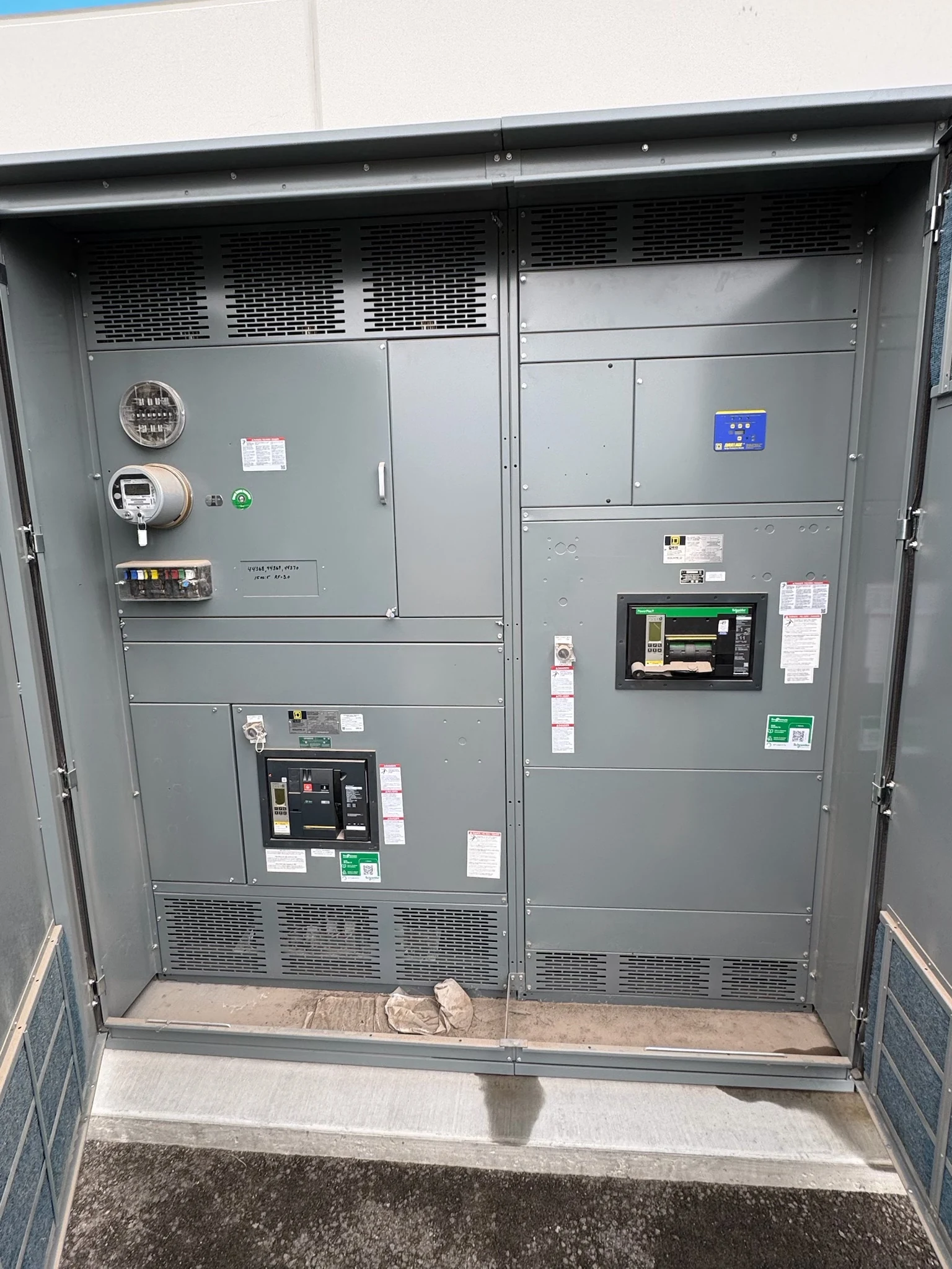
A switchgear bill of materials (BOM) translates an approved design into the components and materials needed for a new distribution assembly. It is more than a shopping list: clear descriptions, quantities and revision history help engineers verify the design while contractors and owners understand what is included. A useful BOM also exposes sourcing and approval decisions before they disrupt procurement or installation.
Start with a defined design basis
Provide the manufacturer with the current one-line diagram, equipment specification, load and feeder schedules, available fault-current information, and any utility requirements. Identify system configuration, enclosure environment, cable entry, control power, and intended metering or communications. The BOM cannot resolve missing engineering assumptions; flag unresolved inputs so a quotation does not quietly turn them into exclusions.
A one-line shows electrical relationships, while a BOM identifies what must be obtained or fabricated. Link each major line item to a drawing reference, feeder designation, or panel location. For example, a feeder breaker entry should be traceable to its circuit on the one-line and to its position in the equipment elevation.
Write descriptions that distinguish function
A useful device entry identifies the manufacturer and part number when specified, quantity, and relevant characteristics rather than simply saying “breaker.” Depending on the design, those characteristics may include voltage and continuous-current ratings, interrupting duty, trip functions, poles, mounting arrangement, and accessories. The engineer must evaluate the device together with the assembly and available fault current.
Include less visible items that affect operation and cost: protective relays, instrument transformers with specified ratios and accuracy, terminal blocks, control-power devices, wiring, labels, and enclosure hardware. Describe bus and connection provisions at the level needed for purchasing and review. A detailed component list does not itself establish an assembly rating or listing.
Make sourcing requirements explicit
Separate a named, mandatory component from a preferred product or a performance-based requirement. If domestic origin or a particular supply-chain rule applies, identify the governing contract language, the components covered, and the evidence required. Manufacturing the assembly in the United States does not by itself establish the origin of every component.
Ask the manufacturer to identify items with sourcing uncertainty and to confirm availability and documentation before committing to a particular component. The purchasing team can then compare proposals on an equivalent scope, including accessories and required records, rather than treating a shorter list as proof of a lower total project cost.
Review alternates as engineering changes
A substitute that fits the panel is not automatically equivalent. Compare electrical duty, protective functions, interfaces, physical dimensions, operating accessories, control voltage, and maintenance implications against the specified device. A relay alternate, for instance, may require different instrument-transformer inputs or communications mapping even when its basic protection functions appear similar.
The manufacturer should document proposed deviations and supporting data for review by the specifying engineer and other required project authorities before purchase or incorporation. Verify any effect on assembly construction and the required listing; for an applicable switchboard, confirm the project-specific UL 891 listing scope rather than assuming a component substitution preserves it.
Use the BOM to manage schedule dependencies
Map major components to submittal review, approval, purchasing, fabrication, assembly, and testing milestones. A device cannot be treated as released for procurement merely because it appears in a preliminary BOM. Identify decision deadlines and the effect of delayed approvals or design changes on the overall project schedule, without assuming a fixed lead time.
The contractor should coordinate field cable, termination, foundation, and installation interfaces with the drawings, while the owner identifies required operating features and spare parts. Distinguish components supplied with the assembly from field-furnished items. This prevents a communications gateway, termination kit, or control-power source from falling between purchase orders.
Control revisions through final handoff
Keep a revision-controlled register showing the affected item, old and proposed descriptions, reason for change, disposition, approver, and schedule or cost impact. Reconcile the released BOM with approved drawings and any accepted exceptions; after changes, update cross-references so the installer can identify the actual interfaces rather than relying on an outdated schedule.
At turnover, request the agreed final parts list, equipment drawings, device literature, and applicable inspection or test records. Identify who supplies settings, performs field connections, and accepts the equipment. Qualified electrical personnel must plan and perform site work under applicable procedures and manufacturer instructions; the BOM supports that work but is not an operating procedure.
LET'S BUILD SOMETHING RELIABLE — 03
Ready to talk
switchgear?
Tell us about the new equipment your project needs. Include as much or as little detail as you have today.
(951) 403-5738CALL TO DISCUSS YOUR PROJECT