
BUILT IN THE USA. READY FOR YOUR PROJECT.
Top vs. Bottom Cable Entry
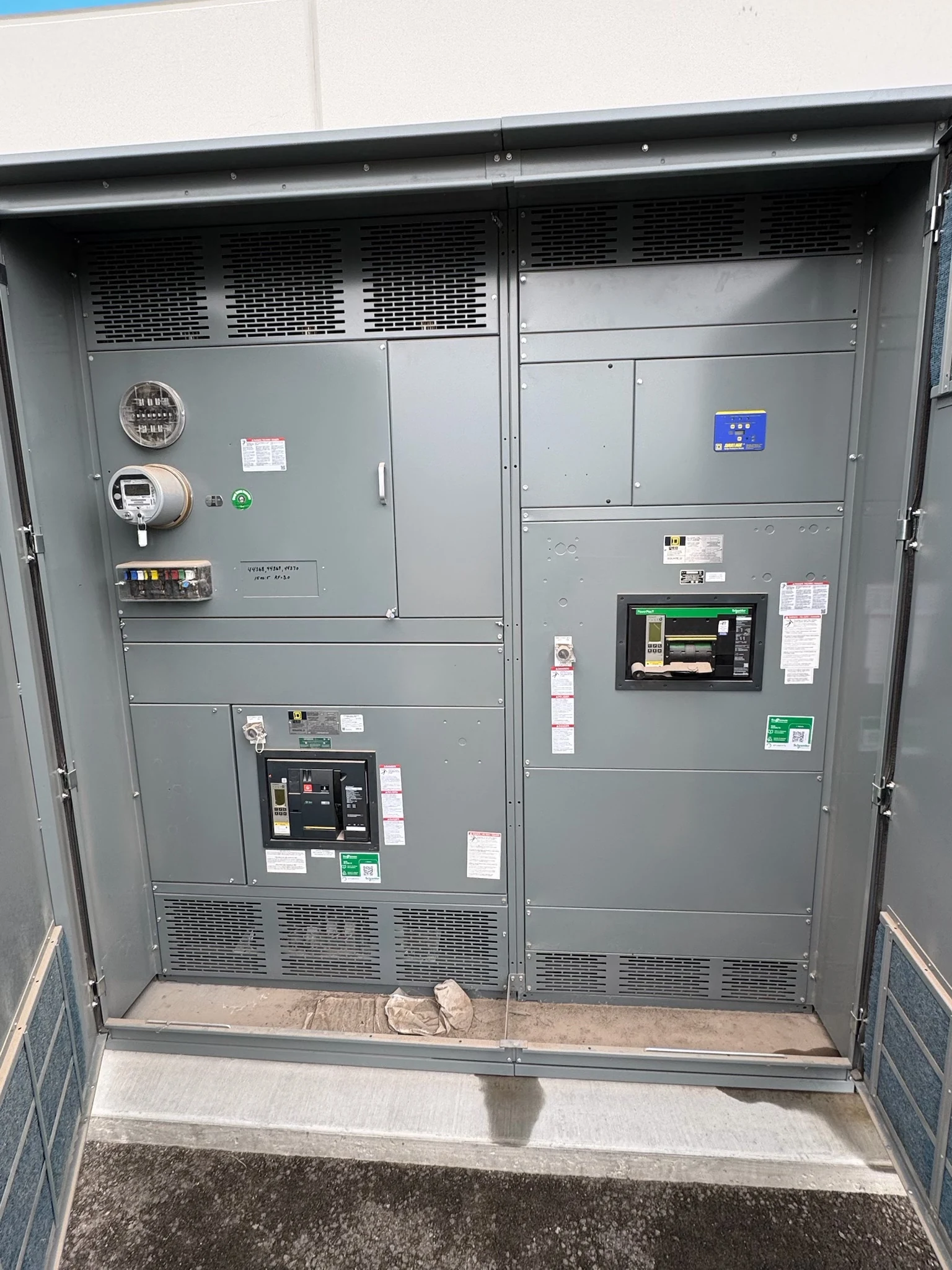
A top or bottom cable entry decision determines more than where conduit meets a switchboard or switchgear enclosure.
DIRECT FROM THE MANUFACTURER / NEW EQUIPMENT
THE MANUFACTURER’S PERSPECTIVE — 02
A top or bottom cable entry decision determines more than where conduit meets a switchboard or switchgear enclosure. It shapes the route from transformers and loads, the room needed to bend and terminate conductors, and how future work fits around the equipment. Engineers, contractors and facility owners should settle the entry concept early, then confirm the details with the manufacturer and installation team.
Follow the route into the room
Top entry can fit an overhead cable tray or conduit system and avoid a floor trench. Its apparent simplicity depends on available ceiling height, structural support, other overhead services and a clear route into the designated cable compartment. A shorter overhead run is not automatically cheaper if supports, coordination or an added pull box are needed.
Bottom entry can suit underground conduits or a cable trench and keep overhead space available. It also ties the equipment location closely to the slab, conduit stub-ups and any drainage or water-sealing details. Moving the lineup later may be difficult if the underground route is already fixed; review possible flooding and soil or moisture exposure during design.
Make bending space a design input
A cable can physically reach an enclosure opening yet lack room to turn toward its terminal without excessive bending. Conductor size, insulation, cable construction, number of parallel runs and the orientation of the lugs all affect the space needed. Check the applicable code, cable manufacturer requirements and equipment termination details together rather than relying on a generic clearance.
Ask for an elevation and a sectional view showing the proposed entrance, cable paths and termination area. A larger cable compartment or separate pull section may resolve a crowded arrangement, but it adds footprint, height or cost. In tight rooms, compare those consequences with rerouting the raceway before selecting the lineup dimensions.
Check where the conductors actually land
The entrance location does not, by itself, establish the direction or accessibility of the terminals. Confirm the positions of phase, neutral and equipment grounding connections, along with the intended conductor material, size, quantity and terminal compatibility. Lug type and the space for parallel conductors should be shown on the equipment submittal, not assumed from a one-line diagram.
Consider access for installation, inspection and future replacement when choosing between front and rear termination arrangements, where offered. Compartments, barriers and adjacent sections can limit the usable working space. The engineer and manufacturer should also coordinate conductor grouping and any ferrous enclosure or raceway interfaces to address potential heating and the applicable installation requirements.
Protect the enclosure and site interfaces
Top openings may compete with bus, ventilation, lifting provisions or overhead obstructions; bottom openings may intersect base members, anchors, internal barriers or cable supports. Provide a dimensioned entrance area for review before concrete or fabrication is committed. Do not assume the contractor can create an opening anywhere without affecting the assembly design.
Identify whether the location is indoors or outdoors and communicate exposure to water, dust or corrosive conditions. The approved entry arrangement, fittings and sealing approach must preserve the enclosure properties required for that project. Where a listed switchboard is specified, confirm that the proposed entry and field modifications are consistent with its actual listing and manufacturer instructions.
Coordinate power, controls and future capacity
The incoming feeder is only part of the routing picture. Outgoing circuits, metering wiring, communications and control conductors may require separate pathways or segregation according to the design and applicable requirements. Show which cables enter each section and identify interfaces with the transformer, utility service equipment and downstream distribution when applicable.
A future feeder may need an available entry area as well as electrical capacity. Reserve the space in drawings and discuss any provisions with the manufacturer instead of assuming unused metal can be opened later. Compare that allowance against present room constraints and cost, and document any space intentionally left unallocated.
Turn the choice into a procurement package
For a useful quotation, provide the one-line diagram, room plan, equipment elevations, proposed entry direction and routing, conductor and conduit schedules, environmental conditions, required clearances and relevant project specifications. Flag uncertain cable sizes or utility requirements as open items. A direct manufacturer of new assemblies can review these interfaces before the design is released for fabrication.
Request approval drawings with overall dimensions, entrance zones, termination details and the boundaries between factory work and field work. Coordinate drawing review, slab or overhead work and delivery sequencing with the contractor; unresolved entry details can delay fabrication or installation. Qualified persons should perform electrical work under applicable codes, site procedures and manufacturer instructions.
LET'S BUILD SOMETHING RELIABLE — 03
Ready to talk
switchgear?
Tell us about the new equipment your project needs. Include as much or as little detail as you have today.
(951) 403-5738CALL TO DISCUSS YOUR PROJECT