
BUILT IN THE USA. READY FOR YOUR PROJECT.
Insulated Bus and Barriers
Busbar insulation and physical barriers address different risks inside a power-distribution assembly.
DIRECT FROM THE MANUFACTURER / NEW EQUIPMENT
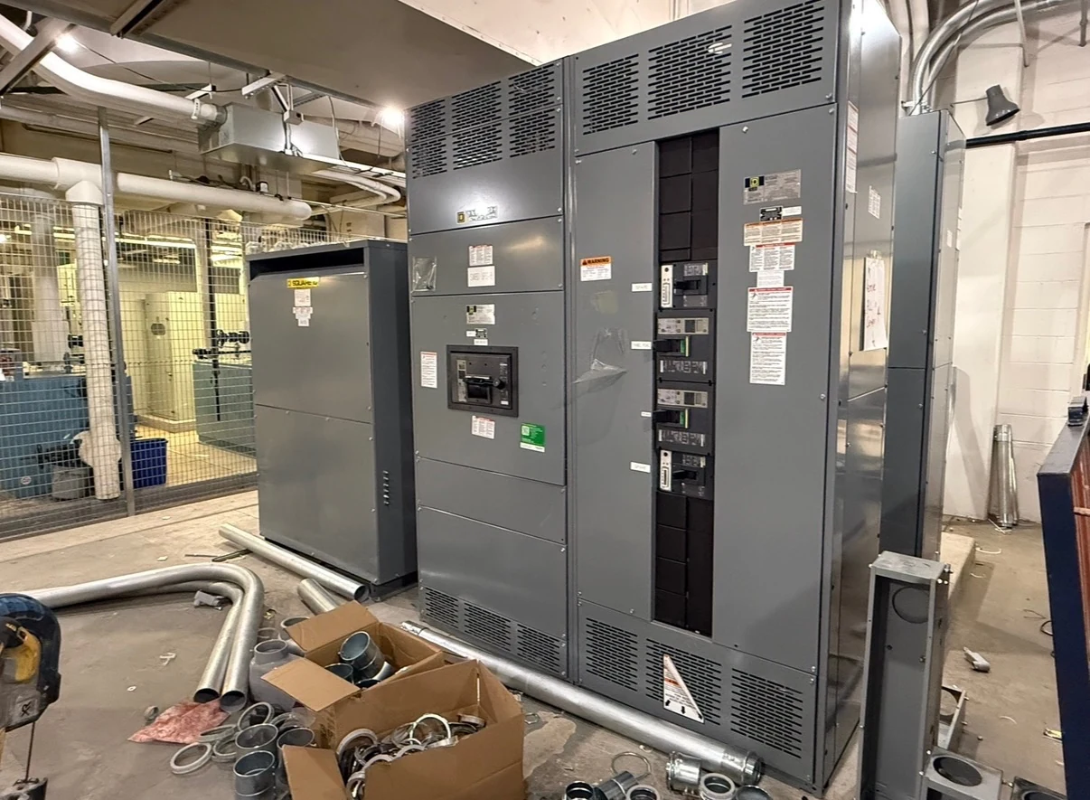
THE MANUFACTURER’S PERSPECTIVE — 02
Busbar insulation and physical barriers address different risks inside a power-distribution assembly. Insulation surrounds or covers a conductor; a barrier separates spaces or restricts access to particular parts. Neither choice automatically makes an assembly suitable for every environment or maintenance practice. For a new lineup, the useful question is how these features work with the complete electrical, thermal and mechanical design.
Choose protection by location, not appearance
Insulating sleeves, coatings or molded coverings may limit exposed conductor surfaces, while insulating or metallic barriers can separate phases, sections or accessible compartments. A metallic barrier must be incorporated into the grounding and bonding design. Each approach changes what an inspector can see and how connections are reached; coverage should be defined on the drawings rather than assumed.
A fully covered-looking bus is not necessarily insulated at every joint, terminal or transition. Removable joint covers can improve access, but they add parts and interfaces that need to fit properly. Ask the manufacturer to identify intentionally exposed areas and explain which barriers or covers are removable for qualified maintenance.
Keep electrical duty and heat in the same review
Give the design team the system configuration, nominal voltage, required equipment voltage class, continuous current and available short-circuit duty, including alternate sources where relevant. Insulation selection and physical spacing belong to the assembly design; material thickness or a barrier alone does not establish an acceptable voltage or short-circuit rating.
Coverings and partitions can affect air movement and heat dissipation around bus joints. They also interact with bus supports that must withstand fault forces. The engineer and manufacturer should evaluate insulation, clearances, temperature performance and mechanical bracing together, rather than substituting a different covering after the design is approved.
Describe the actual contamination exposure
Dust, conductive particles, moisture and chemical deposits can collect on surfaces and degrade insulation performance, particularly when condensation creates a conductive path. Explain whether the equipment room faces process dust, washdown nearby, humidity swings or corrosive vapors. Indoor placement alone does not describe the exposure well enough to choose an enclosure or internal construction.
Barriers may shield one area while creating surfaces where deposits are difficult to inspect. A more restrictive enclosure can reduce exposure but may complicate ventilation or access. Coordinate room conditions, enclosure selection and any proposed condensation control with the project engineer; verify the effect on the complete assembly rather than treating insulation as a substitute for environmental control.
Plan joints, connections and shipping splits
Cable terminations, busway connections and inter-section joints often interrupt a continuous insulating system. Provide conductor quantities and sizes, entry direction, termination details, busway interface drawings and physical access constraints. The manufacturer can then identify where transition pieces, joint covers or barriers are needed and what field connection space must remain available.
If a lineup must ship in sections, request drawings showing the split locations and the insulation and barrier components supplied for those interfaces. Agree which work belongs to the factory and which belongs to the installing contractor. Handling requirements, assembly instructions and a field inspection record help prevent misplaced covers from becoming a late commissioning issue.
Specify evidence and maintenance information
Submittals should identify barrier materials and locations, bus and joint-cover arrangements, enclosure details and any project-specific exceptions. Define the required factory inspection and test records, including acceptance criteria and responsibility for witnessing or reviewing results. For an appropriate switchboard, verify the specific assembly listing and whether the proposed construction falls within its scope; do not infer it from a component label.
Ask for maintenance instructions that identify inspection access, approved cleaning methods, replacement parts and conditions that require engineering review. Insulation can conceal joints, so a visual check of exterior surfaces may not reveal every problem. Inspections and any testing must be planned and performed by qualified personnel under site safety procedures and the manufacturer’s instructions.
Turn the design into a comparable purchase
When requesting a quotation for a new assembly, include the one-line diagram, load and fault information, environmental description, available dimensions and access priorities. State whether barriers are needed between phases, compartments or other defined locations, and identify the documentation and inspection scope. A direct manufacturer can review these inputs against the proposed construction and flag unresolved interfaces.
Compare proposals for what is actually covered, how joints remain accessible, included testing and documented exceptions—not simply whether they mention insulated bus. Set review milestones for drawings and material decisions before fabrication commitments, then coordinate shipping splits, installation and commissioning with the contractor. Changes to coverings or barriers may require renewed engineering review and affect the schedule.
LET'S BUILD SOMETHING RELIABLE — 03
Ready to talk
switchgear?
Tell us about the new equipment your project needs. Include as much or as little detail as you have today.
(951) 403-5738CALL TO DISCUSS YOUR PROJECT