
BUILT IN THE USA. READY FOR YOUR PROJECT.
Switchgear System Integration
A switchgear lineup is only one part of a distribution system.
DIRECT FROM THE MANUFACTURER / NEW EQUIPMENT
THE MANUFACTURER’S PERSPECTIVE — 02
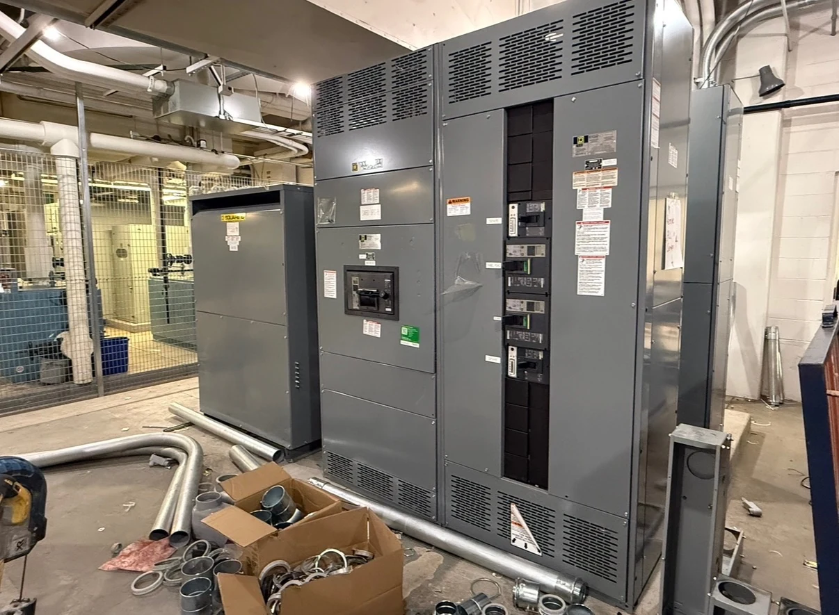
A switchgear lineup is only one part of a distribution system. Its connections to transformers, generators, controls and site wiring determine whether the design can be installed and operated as intended. For specifying engineers, contractors and facility owners, successful integration starts with a shared interface plan—not simply a collection of equipment ratings.
Start with a common system picture
Provide the manufacturer with a current one-line diagram showing sources, transformers, mains, ties, feeders and major loads. Identify nominal voltage, phase and wire arrangement, grounding method, expected demand and future additions. For an operating facility, distinguish verified field conditions from assumptions in older drawings; discrepancies can change both the equipment layout and protection design.
Add available short-circuit information and the intended operating states, including which sources may serve each load. The engineer responsible for the system can then evaluate continuous current, interrupting and withstand duties and protective coordination together. A main breaker that fits the load is not necessarily suitable for every possible source configuration.
Coordinate transformer and generator boundaries
Transformer secondary voltage, impedance and connection arrangement affect the switchgear interface and prospective fault duty. Share terminal locations, conductor or busway details, grounding provisions and any transformer protection requirements. Decide who supplies transitions and supports, and reserve space for field terminations. A compact lineup can be a poor choice if the specified conductors cannot be accommodated.
A generator interface requires more than matching its output to the connected load. Document the start and stop signals, source sensing, neutral and grounding arrangement, and generator protection characteristics. Fault current from a generator may differ from utility contribution, so the project engineer should review settings and ground-fault sensing for each intended source and transfer arrangement.
Define source transfer and interlocks
Where a generator, transfer switch or second utility source is involved, prepare a written sequence alongside the one-line. Describe normal, alternate, maintenance and loss-of-control-power states, including indications and the party authorized to initiate a transfer. Identify whether sources may ever be paralleled; that decision affects the equipment, protection and approvals required.
A responsibility matrix should assign interlocks, permissives, alarms and timing to specific devices and suppliers. Mechanical or electrical interlocks are not substitutes for a complete operating philosophy. Have the engineer and equipment suppliers review abnormal states and recovery expectations, then have qualified personnel verify the approved sequence during commissioning under site procedures.
Make controls and communications testable
List every exchanged signal with its source, destination, purpose and required behavior: for example, generator available, breaker status or remote alarm. Specify contact type, control voltage, power source, terminal assignments and any isolation needs. Agree on what happens if control power or a communications link is lost rather than leaving that behavior to commissioning.
For networked meters or supervisory systems, coordinate protocol compatibility, point mapping, network addressing, time synchronization and access permissions with the owner's controls team. A protocol name alone does not prove that two devices share the required functions. Define the boundary between the equipment network and the facility network, including cybersecurity responsibilities and who supplies configuration files.
Turn the interface plan into an installable layout
Share room dimensions, delivery route, foundation details, environmental conditions and the proposed cable-entry direction before the layout is finalized. The contractor should compare conductor quantity, size and bend space with termination drawings, and coordinate busway alignment where applicable. The design team must review working clearances, ventilation and access against the actual equipment and applicable requirements.
Shipping splits can make a large lineup easier to transport, but they add alignment and field-connection work. Identify lifting provisions, shipping weights, anchor locations and field assembly responsibilities in the submittals. Site conditions or a late change in transformer location can affect connections and access, so route revisions through the same drawing-review process as electrical changes.
Buy against deliverables and a coordinated schedule
When requesting a quotation for newly manufactured equipment from a direct American manufacturer serving San Antonio, South Texas and nationwide, include the interface matrix and required drawings. Compare proposals for included devices, control wiring, transitions, testing, documentation and exceptions—not equipment price alone. Assign foundation, field cable, settings, startup and utility coordination explicitly to avoid gaps between contracts.
Build the schedule around approvals, component availability, fabrication, delivery and the contractor's installation and outage plans; confirm milestones with each party rather than assuming a fixed lead time. Specify factory test scope and witness needs, then coordinate site checks of signals, interlocks and protective settings. Turnover should include approved drawings, test records, manuals and documented ownership of remaining commissioning work.
LET'S BUILD SOMETHING RELIABLE — 03
Ready to talk
switchgear?
Tell us about the new equipment your project needs. Include as much or as little detail as you have today.
(951) 403-5738CALL TO DISCUSS YOUR PROJECT