
BUILT IN THE USA. READY FOR YOUR PROJECT.
Metal-Clad Switchgear for Industrial Facilities
A plant’s medium-voltage distribution system must serve large motors and process loads while limiting the consequences of a fault.
DIRECT FROM THE MANUFACTURER / NEW EQUIPMENT
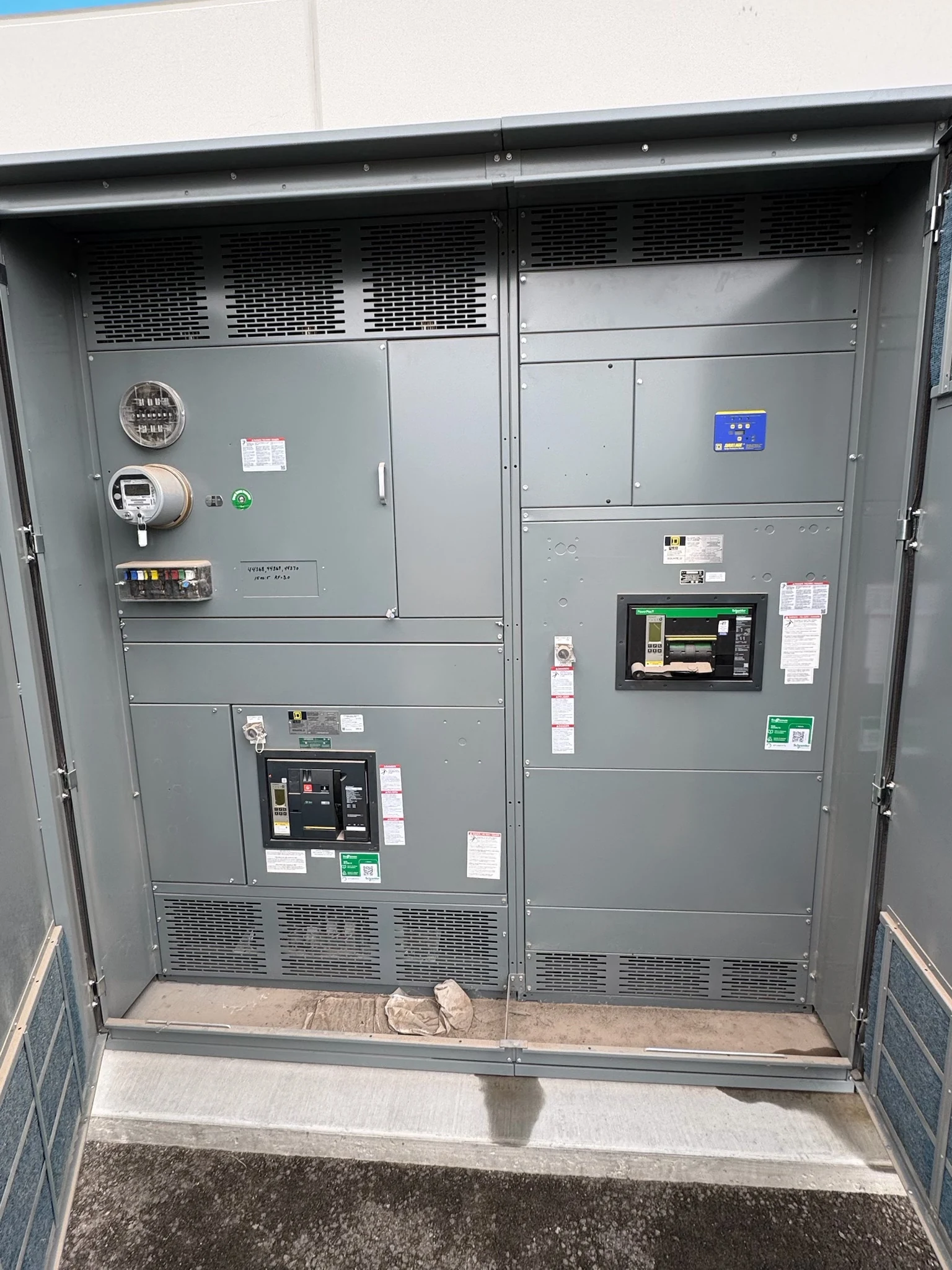
THE MANUFACTURER’S PERSPECTIVE — 02
A plant’s medium-voltage distribution system must serve large motors and process loads while limiting the consequences of a fault. Metal-clad switchgear provides a compartmented approach to switching and protection, but its value depends on the facility’s operating priorities and system design. Owners and specifiers should define those priorities before requesting a new lineup, not after its footprint and feeder arrangement are fixed.
What compartmented construction changes
Metal-clad construction separates major equipment functions with grounded metal barriers and typically incorporates drawout circuit breakers and automatic shutters. These features help organize isolation and maintenance, but they do not make energized work safe or eliminate the need for an outage. Specify the applicable switchgear standard, such as IEEE C37.20.2 where appropriate, and confirm the proposed assembly meets the project requirements.
A more compartmented lineup may require more floor space and investment than another medium-voltage arrangement. Compare that tradeoff with the plant’s maintenance strategy, consequences of a failed feeder and access needs. Ask the manufacturer to identify breaker, bus, cable and instrument compartments on the proposed drawings rather than treating the term metal-clad as a complete specification.
Arrange feeders around the process
Start with a one-line showing incoming sources, transformers, motors, downstream distribution and normal operating states. Identify which production areas can stop together and which require independent restoration. Grouping unrelated critical loads on one feeder can simplify the lineup but may expose a larger part of the process to a single feeder fault.
Where continuity justifies it, a main-tie-main arrangement can provide an alternate supply path, subject to source capacity and an engineered switching philosophy. It adds breakers, controls, space and protection coordination. Define whether source paralleling is permitted, the intended tie state, and interlocks and approvals needed for any transfer; a tie alone does not establish redundancy.
Account for motor starting and drives
For each significant motor, provide its rating, starting method, starting current and duration, expected starts, and driven load. A large motor start can depress voltage for nearby loads even when its normal running current fits the feeder. The engineer should evaluate simultaneous starts, permissible voltage variation and the supply system before selecting feeder and protection arrangements.
Variable-frequency drives change the interface: request drive input characteristics, harmonic information, grounding requirements and any specified filtering. Coordinate cable routing and termination details with the drive supplier. Motor control or drive equipment may sit downstream of the switchgear; draw a clear boundary between the feeder breaker, motor protection functions and the separate control package.
Coordinate fault duty and protection
Obtain source fault contribution, transformer impedance, grounding method and feeder data for the short-circuit and coordination studies. The engineer must check breaker interrupting capability and the assembly’s applicable withstand duties against the calculated conditions, including credible source configurations. Continuous current capacity alone does not establish that a lineup can withstand or interrupt a fault.
Coordinate relay functions and current-transformer ratios, accuracy and burden with the protection study. Settings must distinguish, as far as the design permits, motor starting from faults and allow a downstream device to clear before an upstream device unnecessarily trips. Document study assumptions, trip power and final settings responsibility; selective operation is not automatic across every fault condition.
Fit the electrical room and control system
Provide the available room dimensions, access routes, cable entry direction, conductor sizes and quantities, and required maintenance clearances. Confirm floor loading, shipping splits, lifting access and cable bending space against the proposed elevations. Dust, moisture, ambient temperature and ventilation can affect enclosure selection and equipment performance, so describe the actual plant environment rather than assuming an indoor room is benign.
Coordinate auxiliary AC or DC control power, breaker status, alarms, trip signals and any plant control-system interface. A point list, communications protocol, network boundary and loss-of-control-power behavior help prevent gaps between switchgear and automation suppliers. Assign each connection and functional test to a responsible party, including the owner’s cybersecurity requirements where remote monitoring is planned.
Purchase against a defined outage plan
A direct American manufacturer serving San Antonio, South Texas and nationwide can review a request for a new assembly using the one-line, load schedule, study inputs, room constraints and required standards. Ask for an itemized scope, ratings subject to engineering review, drawings, protective-device details, factory test plan and documented exceptions. Compare bids on those same boundaries, not only the number of breaker cells.
Agree on drawing review dates, component availability checks, factory test and witness requirements, delivery splits and the target outage window. Design revisions, approvals and long-lead components can change the schedule; confirm milestones rather than assuming a delivery guarantee. Qualified personnel must plan installation, isolation, testing and energization under site procedures, with the owner coordinating process shutdowns and acceptance.
LET'S BUILD SOMETHING RELIABLE — 03
Ready to talk
switchgear?
Tell us about the new equipment your project needs. Include as much or as little detail as you have today.
(951) 403-5738CALL TO DISCUSS YOUR PROJECT