
BUILT IN THE USA. READY FOR YOUR PROJECT.
Low-Voltage Switchgear for Power Plants
Low-voltage power circuit breaker switchgear distributes station-service power to equipment a generating plant needs to start, run, and shut down.
DIRECT FROM THE MANUFACTURER / NEW EQUIPMENT
THE MANUFACTURER’S PERSPECTIVE — 02
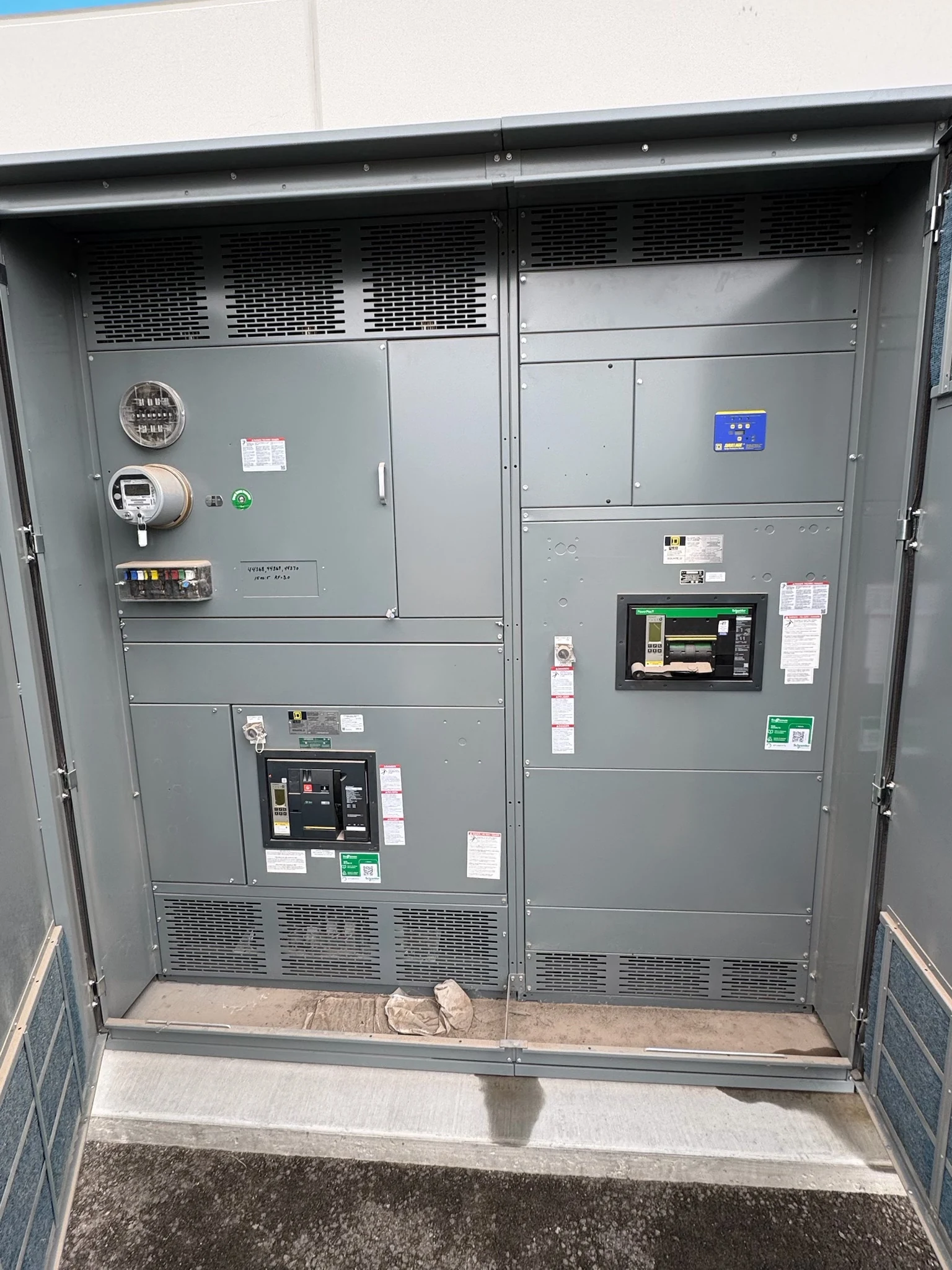
Low-voltage power circuit breaker switchgear distributes station-service power to equipment a generating plant needs to start, run, and shut down. Unlike a typical building service, its buses may operate from different sources as the plant changes state. A useful purchase begins with the actual auxiliary loads, source arrangements, and operating philosophy rather than a generic equipment lineup.
Start with the auxiliary load plan
Identify the motor control centers, cooling pumps, fans, lubrication systems, instrumentation supplies, and battery chargers served by each bus, where those loads are present. Some large motors may connect at another voltage level. A feeder schedule should show operating demand, starting characteristics, criticality, and planned additions instead of assuming that all auxiliaries belong in one lineup.
Ask operations which loads must remain available through a unit trip and which can restart later. Simultaneous motor starting can affect voltage recovery and source capacity, while spare feeders and bus capacity make future changes easier but increase initial scope. The engineer should use the plant load study to distinguish essential capacity from space reserved for uncertain growth.
Define every source and permitted transition
The one-line should identify incoming transformers, generator-related and external sources, bus ties, grounding arrangements, and equipment ownership boundaries. Include source and transformer data for both startup and generation scenarios. A plant may have a different fault contribution and load pattern in each state, so a single normal-running diagram is not enough for equipment selection.
Document which breakers may be closed together and whether transfer is open transition or requires an explicitly engineered synchronization scheme. The owner and engineer should define permissives, interlocks, trip priorities, and responses to a failed source or unavailable control power. These decisions affect breaker arrangements and control wiring; unintended source paralleling must not be left to an informal operating assumption.
Balance fault duty, selectivity, and clearing time
Provide the engineer with maximum and minimum available fault-current information for credible source configurations, including generator and motor contributions where applicable. Compare breaker interrupting capability and the assembly’s withstand duty with the system study, including the duration of any intentional protection delay. Continuous-current selection is a separate question from a breaker’s ability to interrupt a fault.
Selective coordination can limit the extent of an outage, but longer upstream clearing times can affect incident energy and short-time withstand requirements. Review time-current curves and arc-flash results together rather than treating either objective in isolation. Specify the applicable switchgear and breaker standards and verify any required project-specific listing; UL 891 addresses appropriate switchboards, not all switchgear.
Make controls and plant systems agree
A power plant may use protective relays, breaker trip units, a DC control supply, and a distributed control system with different owners. Define the source and voltage of control power, trip and close interfaces, instrument transformer requirements, terminal points, and the desired behavior if that power is lost. Confirm which protection functions and settings belong to each device.
For remote indication or control, agree on the communications protocol, network boundary, point list, alarm priorities, and local-versus-remote authority. A breaker status point alone does not describe the whole transfer sequence. Include a cause-and-effect or interlock matrix and identify who will test each hardwired signal and communications point against the approved logic.
Plan the room around operation and maintenance
Give the manufacturer the proposed room dimensions, cable entry routes, ventilation conditions, and applicable access requirements. Heat, dust, moisture, corrosive exposure, and vibration can influence the enclosure and component choices. Coordinate heat rejection with the room designer and reserve space for cable bends, breaker handling, and future sections without assuming a universal clearance.
Drawout breakers can support a maintenance strategy, but their compartments, handling needs, and costs may differ from a fixed arrangement. Compare these tradeoffs against the plant’s outage plan and the specified equipment design. Maintenance and any field electrical work remain the responsibility of qualified personnel working under site procedures, applicable codes, and manufacturer instructions.
Purchase against an agreed scope and schedule
For a direct-manufacturer quotation, supply the one-line, load schedule, source studies, operating sequence, physical constraints, and required standards. Request drawings showing elevations, feeder connections, device schedules, controls, and exceptions. Define factory inspection or witness-test scope, acceptance criteria, and final records; pricing depends on the selected duties, devices, enclosure, and documentation.
Coordinate drawing approval, component procurement, fabrication, testing, shipping, and the plant outage window before committing to a schedule. Clarify who supplies foundations and field cables, develops protective settings, integrates controls, and authorizes commissioning. The manufacturer supplies new assemblies for projects in San Antonio, South Texas, and nationwide; project-specific availability and delivery dates require confirmation.
LET'S BUILD SOMETHING RELIABLE — 03
Ready to talk
switchgear?
Tell us about the new equipment your project needs. Include as much or as little detail as you have today.
(951) 403-5738CALL TO DISCUSS YOUR PROJECT