
BUILT IN THE USA. READY FOR YOUR PROJECT.
High-Voltage Switchgear: Protection and Coordination
High-voltage switchgear protection starts with more than selecting a breaker.
DIRECT FROM THE MANUFACTURER / NEW EQUIPMENT
THE MANUFACTURER’S PERSPECTIVE — 02
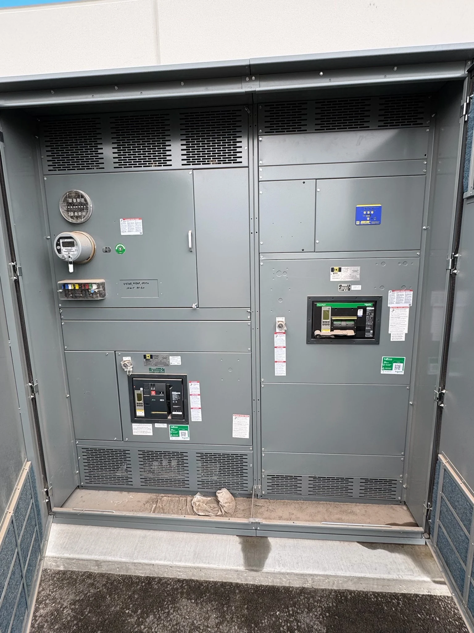
High-voltage switchgear protection starts with more than selecting a breaker. The equipment must fit the power system’s fault levels, operating arrangements and protection philosophy, while giving the study engineer reliable information for coordination. Owners and contractors considering a newly manufactured assembly should establish those requirements early: the appropriate design and even manufacturing feasibility depend on the actual application.
Define the system the gear must protect
Provide a current one-line showing the utility connection, transformers, generators, buses, ties and outgoing circuits. Identify normal and alternate configurations, grounding method, source impedances and planned expansion. The utility and project engineer should establish which information is available and who will resolve missing data before the manufacturer commits to a design.
The short-circuit study should address both maximum and minimum credible fault levels at the proposed location, including relevant source and tie positions. Maximum duty influences equipment selection; minimum fault current matters because a protective function must still detect faults reliably. Include forecast system changes and the assumptions behind the study rather than relying on a single unexplained number.
Separate interrupting duty from withstand
A breaker must be evaluated for the system voltage and the applicable interrupting duty, including the fault-current characteristics and recovery conditions specified by the governing equipment standard. The assembly’s bus and other current-carrying parts also need appropriate peak and short-time withstand capability. Continuous current capacity alone does not establish fitness for a fault.
The duration for which the assembly must withstand current depends on the protection and clearing strategy. A deliberate delay may improve selectivity but can increase withstand requirements. Ask the manufacturer to identify the rating basis, switching duties, insulation requirements and any limitations of the proposed configuration; the engineer should compare them with the project study.
Choose protection around the circuit
Protection can combine functions rather than relying on a single setting. Depending on the network and study, overcurrent and ground-fault protection may be supplemented by differential or distance functions. Transformer, bus and feeder schemes have different zones and information needs; a multi-source system can require direction-sensitive elements to distinguish where a fault lies.
A more comprehensive scheme can improve discrimination or speed, but it adds devices, wiring, engineering and testing. Define primary and backup protection, breaker-failure response and the intended trip boundaries with the utility and engineer of record. Do not assume that adding a relay automatically provides the required coverage or coordination.
Coordinate speed, selectivity and consequences
The coordination study compares protective characteristics over the relevant fault-current range, including upstream and downstream devices. Its objective is to isolate the affected portion where practicable while retaining backup protection. For a feeder fault, a downstream device may need time to clear before the upstream breaker responds; the available margin depends on the actual devices and currents.
Faster clearing can reduce exposure and equipment stress, while longer delays may preserve service to unaffected loads. Neither outcome is assured by a generic setting. The study should document coordination limits, clearing times and any impact on an arc-flash assessment; the owner and engineer must decide which tradeoffs meet the facility’s operating priorities.
Specify sensing and trip interfaces
Current and voltage transformers connect the power circuit to the relays. Provide required ratios, accuracy, burden and winding assignments, and have the protection designer evaluate current-transformer saturation for the intended fault duty. Utility metering and protective relaying may have distinct interface requirements, so their terminals and responsibilities need explicit agreement.
Document the control-power source, trip and close circuits, supervision, alarms, interlocks and any remote indication or communications points. Loss of control power or communications should be addressed in the protection and operating philosophy. Identify who supplies batteries, external wiring and network equipment, and which signals must be proven during commissioning.
Turn study assumptions into an order
For a meaningful quotation, submit the one-line, duty study or available source data, protection narrative, environmental and insulation criteria, applicable standards, required documentation and desired schedule. Ask the direct manufacturer to confirm engineering feasibility, offered equipment scope and exceptions, as well as the proposed division between factory and field work.
Coordinate review of drawings, device data, relay interfaces and proposed factory tests before procurement decisions become fixed. The project schedule should allow for study completion, approvals, component availability, fabrication and witnessed testing if specified. A qualified study provider approves settings; qualified personnel handle installation, testing and energization under site procedures, with final records and settings handed to the owner.
LET'S BUILD SOMETHING RELIABLE — 03
Ready to talk
switchgear?
Tell us about the new equipment your project needs. Include as much or as little detail as you have today.
(951) 403-5738CALL TO DISCUSS YOUR PROJECT