
BUILT IN THE USA. READY FOR YOUR PROJECT.
Low-Voltage Switchgear: New Equipment Replacement Planning
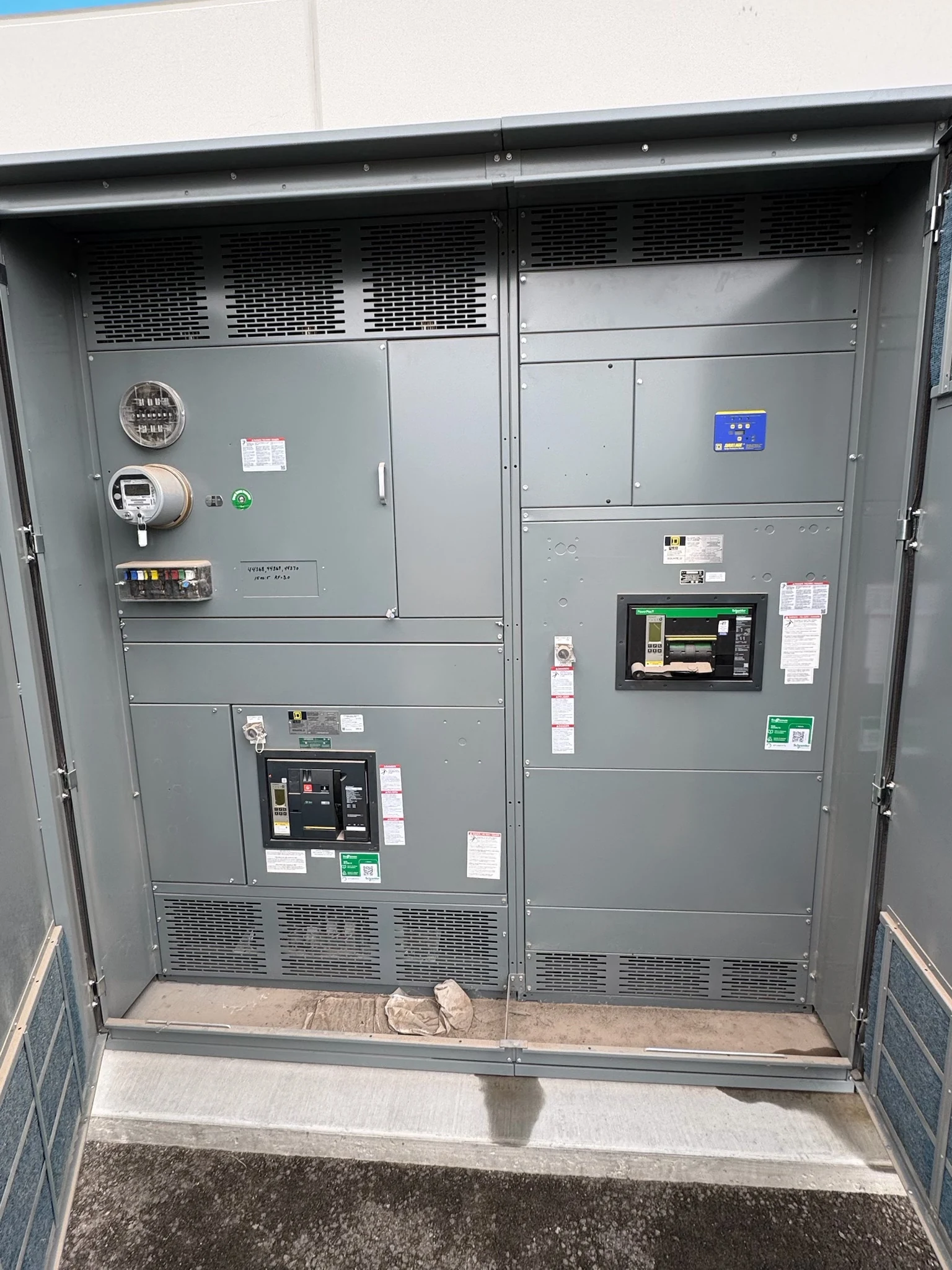
Replacing a low-voltage power circuit breaker switchgear lineup is a system change, not simply a matter of matching its outside dimensions.
DIRECT FROM THE MANUFACTURER / NEW EQUIPMENT
THE MANUFACTURER’S PERSPECTIVE — 02
Replacing a low-voltage power circuit breaker switchgear lineup is a system change, not simply a matter of matching its outside dimensions. Owners, engineers and contractors need a clear record of the existing interfaces and a workable outage strategy before specifying newly manufactured equipment. Early coordination with a direct manufacturer makes it easier to expose conflicts while design choices are still open.
Build a reliable interface record
Start with the current one-line diagram, equipment nameplates, feeder schedule and available drawings. Identify each incoming source, main and tie breaker, outgoing circuit, control supply and connected load. Record discrepancies between documents and the observed installation; an unlabeled feeder can change both the replacement layout and the outage plan.
Have qualified personnel collect dimensions and condition information under site safety procedures. Document cable entry direction, conductor quantity and size, termination locations, busway connections, grounding interfaces and accessible photographs. Existing conductors might not reach a new termination position, so the contractor and engineer should evaluate routing, usable length and any required new connections.
Recheck electrical duty and protection
The engineer should confirm system voltage and configuration, expected load, available fault current and upstream clearing characteristics rather than copying a nameplate as the entire specification. The new assembly, bus and power circuit breakers need project-appropriate continuous-current, interrupting and withstand capabilities, evaluated together for the actual sources and operating configurations.
A protection and coordination review can identify whether new trip units, ground-fault functions or altered settings affect upstream and downstream devices. Provide available study results and load growth assumptions to the manufacturer. The study provider remains responsible for calculating and documenting final settings; a replacement breaker is not automatically coordinated because it occupies the same circuit position.
Fit the lineup to the room and the work
Measure the full delivery path as well as the final footprint: door openings, turns, floor loading, lifting access and the available staging area matter. Include applicable working clearances and the space needed to handle drawout breakers, open doors and reach cable compartments. The project team should verify clearance requirements for the actual installation.
A compact arrangement may reduce its footprint but restrict termination or maintenance access. Shipping splits can make a difficult route possible, while adding field assembly and inspection work. Coordinate section dimensions, weights, anchorage, floor tolerances and ventilation with the contractor and structural or mechanical designers before approving the equipment layout.
Let the owner lead the outage strategy
The owner should identify critical loads, permitted interruption windows, stakeholders and decision authority. With the engineer and contractor, compare a single replacement outage with a phased cutover. Phasing can protect operations, but it may require additional temporary boundaries, connection work and approvals; it should not be assumed feasible from a schedule alone.
If temporary power is contemplated, establish its capacity, connection points, protection and responsibilities in a separate engineered plan. The owner should approve a sequence covering dependencies, communications, contingencies and a return-to-service decision. Qualified persons perform isolation and verification under site procedures and applicable requirements; the manufacturer supplies equipment information needed for planning.
Resolve controls and breaker choices early
Identify the signals that must cross the new lineup boundary: remote breaker status and commands, metering data, alarms, interlocks and generator or transfer-system interfaces. Provide control voltage, communication protocol, point lists and operating narratives. Assign integration ownership so that a complete power circuit does not conceal an unfinished control connection.
Discuss fixed versus drawout breaker arrangements against maintenance objectives, available space and project requirements. Drawout construction can support a defined maintenance strategy, but its access needs and configuration must fit the engineered assembly. Confirm the specified equipment standard and any project-required listing for the actual construction; do not infer approval from visual similarity.
Purchase against deliverables and hold points
Ask the manufacturer for a proposal tied to the latest one-line, feeder schedule, site constraints and outage assumptions. Compare equipment scope, device functions, ratings to be verified, exceptions, drawing submissions, test scope and shipping splits. Name who provides field wiring, installation, protection settings, temporary power and commissioning rather than leaving gaps between contracts.
Set review milestones for approval drawings, release of long-procurement components, factory checks, delivery and site acceptance. Agree on requested test records, manuals, as-built information and interface drawings. Actual timing depends on design approval, component availability and site readiness. The owner authorizes return to service only after qualified personnel complete the project-specific checks and required approvals.
LET'S BUILD SOMETHING RELIABLE — 03
Ready to talk
switchgear?
Tell us about the new equipment your project needs. Include as much or as little detail as you have today.
(951) 403-5738CALL TO DISCUSS YOUR PROJECT