
BUILT IN THE USA. READY FOR YOUR PROJECT.
Metal-Clad Switchgear: Selection and Equipment Scope
Metal-clad switchgear is a medium-voltage distribution assembly selected for more than its nominal voltage and feeder count.
DIRECT FROM THE MANUFACTURER / NEW EQUIPMENT
THE MANUFACTURER’S PERSPECTIVE — 02
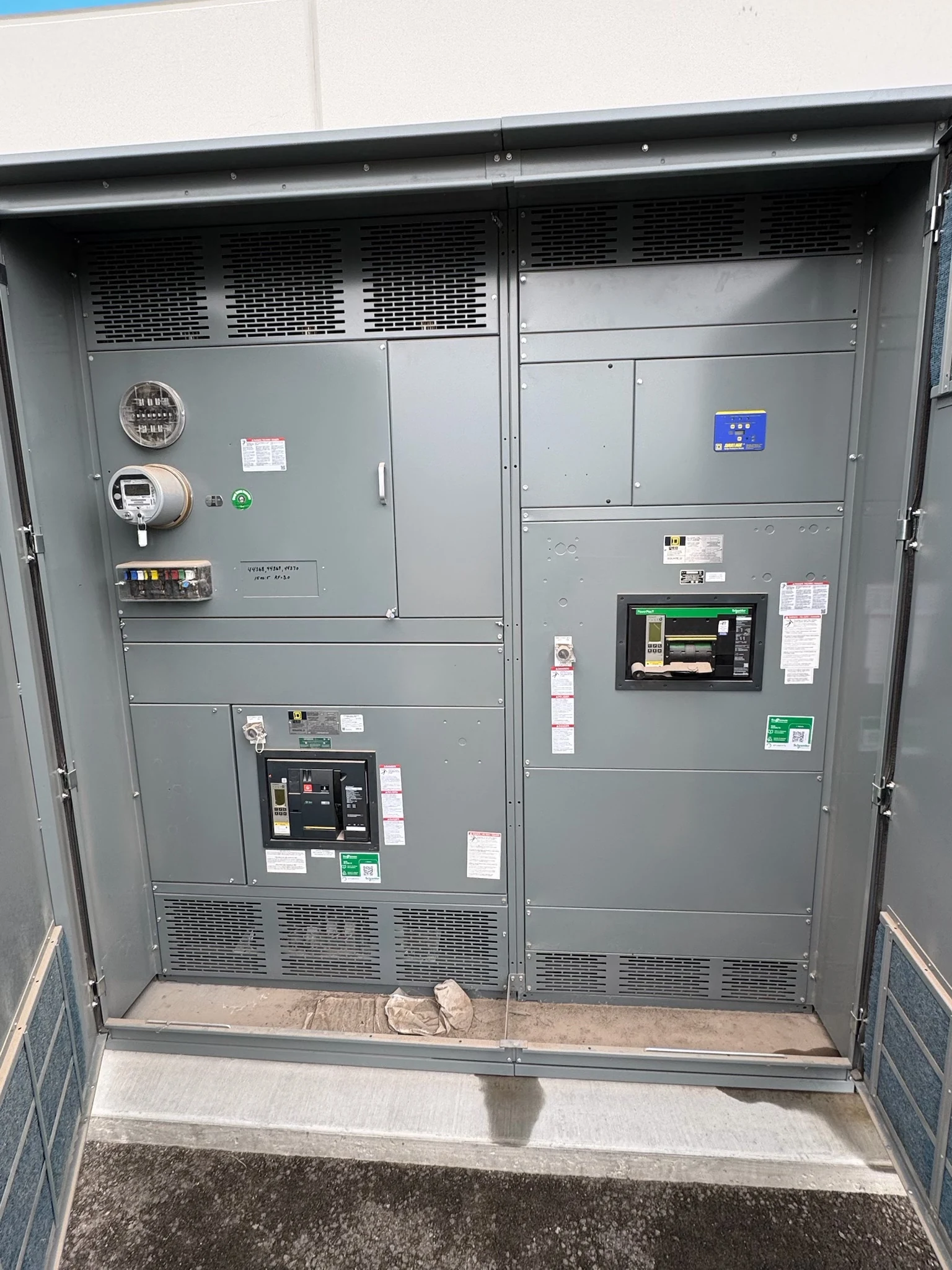
Metal-clad switchgear is a medium-voltage distribution assembly selected for more than its nominal voltage and feeder count. Its compartmented construction, removable switching devices and protection interfaces must work together as a complete engineered lineup. Owners, engineers and contractors should define the power system and the intended operating environment before comparing a new assembly with alternative equipment.
Decide whether metal-clad construction fits
Metal-clad designs typically separate major elements, such as the main bus, breakers and cable connections, with grounded metal barriers. Insulated bus, withdrawable breakers, shutters and interlocks are characteristic features to verify against the applicable equipment standard and the submitted design. Ask which compartments require access for the planned inspection and maintenance activities.
This architecture can support a structured maintenance strategy, but it also affects lineup size, complexity and purchase scope. A metal-enclosed assembly with a different switching arrangement may suit some projects; the labels are not interchangeable. Compartmentation alone does not make an assembly arc-resistant or eliminate electrical hazards.
Match ratings to the actual power system
Provide the one-line diagram, nominal system voltage, frequency, grounding method, source configuration and feeder load schedule. The engineer can then evaluate the equipment voltage class, insulation requirements, continuous current and thermal conditions. Include projected load growth and any anticipated spare feeder positions, rather than assuming an empty compartment automatically supports a future circuit.
Fault duty requires a separate review. Supply available short-circuit current, relevant source characteristics and expected clearing times from the utility or a system study. The complete assembly and its breakers need suitable interrupting and withstand capabilities for the calculated duty; matching a breaker current rating to the load does not establish that fit.
Specify protection and control interfaces
Identify the main and feeder protection functions, relay preferences and proposed instrument transformer inputs. Current transformer ratios, accuracy and burden should be coordinated with the protection and metering design. Where voltage transformers are required, define their connections and functions. Provide the study engineer with the device data needed for coordination and settings.
Clarify whether control and tripping power comes from a dedicated source, an auxiliary transformer or a station battery supplied elsewhere. Specify monitoring for loss of control power, any transfer logic, remote indications and communications. The quote should identify who supplies relay settings, network configuration and field integration; those services should not be presumed included.
Plan safe access and operating needs
Compare the required breaker positions, mechanical interlocks, key schemes and indication with the owner’s intended operating philosophy. For multiple sources or a bus tie, describe permitted source combinations and the conditions that prevent unintended paralleling. A clear sequence of operation helps reviewers evaluate the control design before fabrication.
If arc-resistant construction is specified, state the required accessibility and applicable test standard, then verify the proposed assembly and its installed configuration against the manufacturer’s documentation. Pressure relief paths, ducts and room geometry can affect the design. Qualified personnel must plan all work under site safety procedures, applicable codes and equipment instructions.
Resolve the building and field boundaries
Identify indoor or outdoor exposure, ambient conditions, altitude, moisture and contamination. These inputs affect enclosure, ventilation, heaters and any project-specific rating adjustments. Share the equipment-room layout, access route and required working space early: the footprint must accommodate cable compartments, breaker handling and maintenance as well as the assembled lineup.
Show incoming and outgoing cable sizes, quantities, entry direction, shield termination and grounding expectations. Coordinate support, bending space and termination responsibilities with the installer. Request shipping dimensions, weights, lifting provisions and field splice details, and determine who designs the foundation and anchorage. These interfaces can change both the lineup arrangement and site schedule.
Compare complete proposals and milestones
A useful request for quotation includes the one-line, load and fault data, specifications, site constraints, required standards and a list of exceptions that must be disclosed. Ask the direct manufacturer to identify the proposed equipment scope, engineering assumptions, components, factory test plan and any items requiring separate approval or feasibility review.
Compare submittal drawings, protection and wiring diagrams, test records and final manuals alongside commercial terms. Establish dates for information release, drawing review, component procurement, factory testing, shipping and field commissioning; unresolved approvals can affect later milestones. For projects in South Texas or elsewhere, assign installation, independent studies and energization authorization to the appropriate qualified parties.
LET'S BUILD SOMETHING RELIABLE — 03
Ready to talk
switchgear?
Tell us about the new equipment your project needs. Include as much or as little detail as you have today.
(951) 403-5738CALL TO DISCUSS YOUR PROJECT