
BUILT IN THE USA. READY FOR YOUR PROJECT.
800-Amp Switchgear: Layout and Connection Planning
An 800-ampere planning target describes a current class, not a complete equipment design or a promise that a particular assembly is available.
DIRECT FROM THE MANUFACTURER / NEW EQUIPMENT
THE MANUFACTURER’S PERSPECTIVE — 02
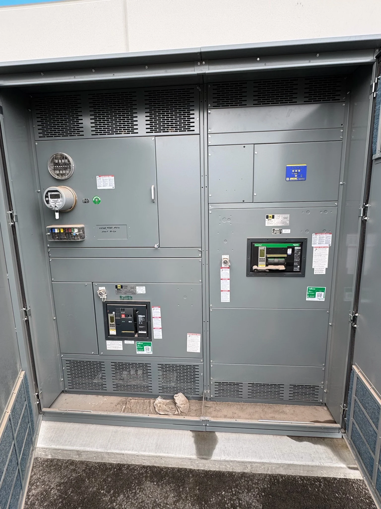
An 800-ampere planning target describes a current class, not a complete equipment design or a promise that a particular assembly is available. The space around the equipment and the way conductors enter it can matter as much as the footprint itself. Owners, contractors and engineers should resolve those interfaces early when requesting a newly manufactured distribution assembly.
Start with the electrical and physical boundaries
Provide the manufacturer with a current one-line diagram, load schedule, system voltage and phase arrangement, source characteristics, and the required main and feeder devices. Identify the available fault current and any required protection or metering. Engineering must confirm actual continuous-current and short-circuit ratings, applicable equipment standards, and availability for the proposed configuration.
Mark the proposed equipment location on a dimensioned plan and indicate adjacent walls, columns, doors and overhead obstructions. A compact lineup may look attractive on a drawing but leave insufficient room for incoming raceways or future feeders. Treat the equipment outline and the space needed to use it as separate design requirements.
Plan each cable approach before fixing the lineup
For every source and feeder, give the conductor material, size, number per phase, insulation, and the intended top or bottom entry. Include neutral and equipment-grounding conductors where required by the design. The design team should verify conductor ampacity and any applicable installation adjustments; the 800-ampere label alone does not determine cable size.
Top entry can simplify overhead routing but competes for space with ducts, trays and building services. Bottom entry may suit underground raceways but depends on slab, trench or conduit locations. Either choice needs sufficient bending and termination space for the actual conductors, not just a convenient opening in the enclosure.
Make termination details part of the order
Ask the manufacturer to identify the proposed terminal locations, conductor range, number of connection points, and any limits on conductor material for each circuit. Parallel conductors can change the number and arrangement of lugs and the space needed to reach them. The engineer and installer should check the selected termination provisions against the field wiring design.
A separate neutral or grounding bus may need its own termination capacity and accessible route. If a transformer, busway or utility service connects directly, exchange interface drawings showing connection elevations, phase arrangement and support responsibilities. Confirm who supplies adapters, transition sections and field connection materials; an unassigned interface can delay installation even when the lineup fits.
Protect access and environmental performance
Review the applicable electrical working space, dedicated equipment space and access requirements with the engineer and authority having jurisdiction. Also show door swing, removable covers and any space needed to handle components. Front access alone should not be assumed: the equipment design and the intended maintenance tasks determine whether other sides need access.
Identify indoor or outdoor placement, ambient conditions, moisture, dust and corrosion exposure. Enclosure construction and ventilation must be compatible with those conditions and the assembly's verified ratings. Routing a pipe or cable tray through a desirable service area can compromise access, while blocking ventilation can change the assumptions behind the thermal design.
Coordinate delivery and field assembly
Compare the proposed shipping dimensions and weights with the unloading point, travel route, door openings and lifting capacity. Large lineups may require shipping splits even where the final room has ample space. Ask for section dimensions, lifting information, anchor locations and the field reassembly requirements before foundations and access routes are finalized.
The contractor, rigging team and manufacturer should agree on where responsibility changes for receiving, placement, connections and inspection. Reserve room to maneuver sections without treating a working clearance as a storage zone. Structural support, anchorage and any seismic requirements belong in the project coordination package rather than being assumed from the ampere class.
Use drawings and review milestones to control risk
A useful quotation request includes the one-line, circuit and cable schedules, room plan, entry preferences, delivery constraints and required documentation. Ask for an outline, elevations, connection locations, shipping splits and a written list of assumptions or exceptions. For an applicable switchboard specification, verify any required UL 891 listing for the specific proposed assembly.
Set review dates for submittals, utility interfaces where applicable, contractor coordination and final release; changes to cable routing or equipment dimensions can affect fabrication and the project schedule. The owner should assign installation, testing and energization to qualified personnel under applicable codes, site procedures and manufacturer instructions. Confirm the actual schedule and deliverables in the project agreement.
LET'S BUILD SOMETHING RELIABLE — 03
Ready to talk
switchgear?
Tell us about the new equipment your project needs. Include as much or as little detail as you have today.
(951) 403-5738CALL TO DISCUSS YOUR PROJECT