
BUILT IN THE USA. READY FOR YOUR PROJECT.
Service Entrance Switchgear: Installation and Access
Service entrance equipment is where a facility’s power distribution meets the utility’s service arrangement.
DIRECT FROM THE MANUFACTURER / NEW EQUIPMENT
THE MANUFACTURER’S PERSPECTIVE — 02
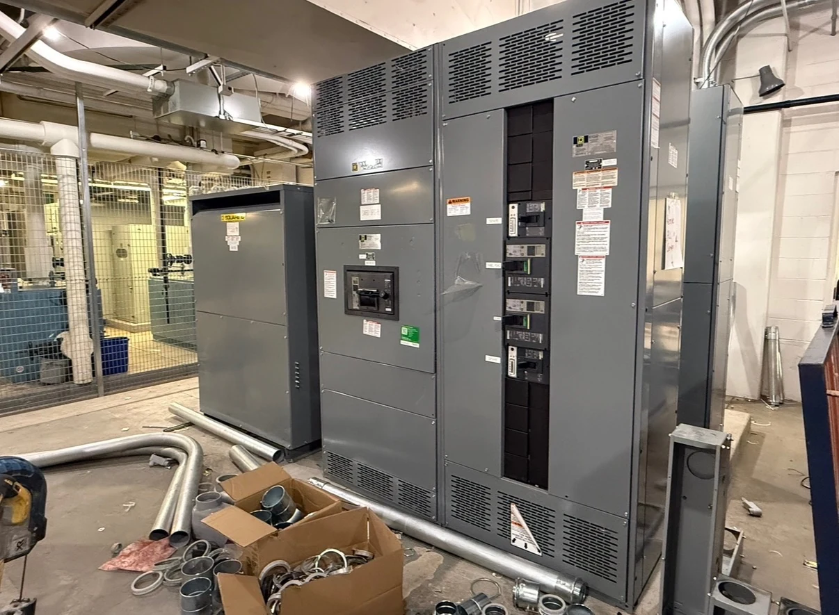
Service entrance equipment is where a facility’s power distribution meets the utility’s service arrangement. A successful purchase depends on more than selecting a main device: the lineup must fit the site, accept the planned conductors, and provide the access required by the utility and the authority having jurisdiction. Owners, engineers and installers should resolve these interfaces before releasing a new assembly for manufacture.
Define the utility boundary first
Start with a one-line diagram showing the utility supply, service point, metering, service disconnect and outgoing feeders. Obtain the utility’s project-specific service characteristics, available fault-current information and metering requirements. The engineer can then establish equipment duties and identify any utility-controlled compartments, seals or access provisions that affect the lineup.
Agree who supplies instrument transformers, meter sockets and associated wiring, and whose approval is needed for their arrangement. A customer monitoring meter is not automatically a substitute for utility revenue metering. Record the utility’s review milestones and any open questions in the equipment submittal so an unresolved interface does not become a field redesign.
Reserve a workable equipment envelope
Give the manufacturer dimensioned room or outdoor pad plans, including structural projections, door swings, finished floor elevations and the route to the service location. Identify front, rear or side access needed for connections and maintenance. A smaller footprint can be attractive, but relocating terminations or adding access restrictions may make installation and later service more difficult.
The design team should verify working space, dedicated equipment space, egress and utility access against applicable rules and the actual layout. Coordinate ventilation and environmental exposure with the enclosure selection, rather than assuming that an outdoor or indoor designation resolves heat, moisture or corrosion concerns. Include room for future sections only where the design supports them.
Resolve cable entry and field interfaces
State whether utility and customer conductors enter from above or below, along with their expected quantity, sizes, material and routing. The manufacturer and electrical contractor can compare conduit locations with termination compartments, bending space and available lug provisions. Bottom entry may simplify an underground route but requires coordination with the pad, sleeves and below-grade obstructions.
Identify phase and neutral arrangements, equipment grounding and the service bonding concept on the engineering documents. The engineer and utility must coordinate which connections belong inside the assembly and which are field responsibilities. Confirm terminal provisions and connection instructions in approved drawings; do not assume that a proposed cable arrangement fits merely because the lineup fits the room.
Plan delivery as part of the layout
Before the order is finalized, compare shipping dimensions and weights with truck access, receiving equipment, door openings and the path to the foundation. A lineup that fits its final position may not pass through an elevator or turn in a corridor. Identify the unloading location, temporary storage conditions and who provides rigging and site protection.
Shipping splits can solve transport restrictions, but they add field alignment and connection work. Ask for section weights, lifting provisions, assembly instructions, anchorage layout and the division of responsibility for rejoining sections. The structural designer should coordinate foundation loads and anchorage with the approved equipment information and site-specific requirements.
Coordinate inspection and turnover
Define factory inspection and any witnessed testing in the purchase scope, including acceptance criteria and the records to be delivered. The installer should receive approved drawings, connection details and manufacturer instructions before field work begins. Separately identify who performs field inspection, required testing, protection settings and corrections if a discrepancy is found.
Utility scheduling, permit inspections and authorization to energize belong in the project plan, not in an assumed manufacturer delivery scope. Qualified electrical personnel must plan and perform installation, testing and energization under applicable site procedures, codes and manufacturer instructions. The owner should receive final drawings, test results and operating and maintenance documentation for turnover.
Compare bids and manage release dates
Request quotations against the same one-line, site plans, utility requirements and equipment specification. Compare the proposed access arrangement, cable provisions, shipping splits, documentation and exceptions as well as the equipment itself. If a switchboard is specified, ask whether a UL 891 listing is required and verify the proposed assembly’s project-specific listing; other equipment types require their own applicable standards review.
A direct manufacturer can review the intended new assembly with the project team, including customers in San Antonio, South Texas and nationwide. Build the schedule around utility responses, drawing review, approval to release, component availability, fabrication, delivery and site readiness. Assign owners and decision dates to outstanding items, and assess changes for both interface and schedule impacts before approval.
LET'S BUILD SOMETHING RELIABLE — 03
Ready to talk
switchgear?
Tell us about the new equipment your project needs. Include as much or as little detail as you have today.
(951) 403-5738CALL TO DISCUSS YOUR PROJECT