
BUILT IN THE USA. READY FOR YOUR PROJECT.
Breaker Interrupting Rating
A breaker interrupting rating describes its ability to clear a short circuit under specified conditions.
DIRECT FROM THE MANUFACTURER / NEW EQUIPMENT
THE MANUFACTURER’S PERSPECTIVE — 02
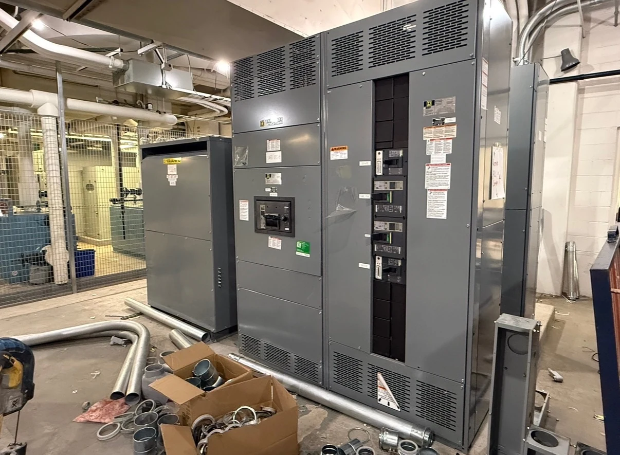
A breaker interrupting rating describes its ability to clear a short circuit under specified conditions. It is not the same as the current a breaker carries during normal operation, and it does not establish the fault rating of the surrounding assembly. Engineers, contractors and facility owners need all three perspectives when specifying new distribution equipment.
What the interrupting number means
For an AC breaker, interrupting capacity is commonly expressed in kiloamperes of symmetrical RMS current at a specified voltage. It represents a tested capability under the applicable device standard and stated conditions, not a measurement of the current that will actually flow at a particular installation. DC applications have their own rating conditions.
As an illustration, a calculated 30 kA available fault at a breaker is below a 42 kA interrupting rating. That comparison alone is not an approval: the engineer must also check system voltage, device application conditions, fault characteristics and the equipment in which the breaker is installed. Different voltage markings can carry different interrupting capacities.
Continuous current answers a different question
The ampere rating associated with carrying load concerns heating and operating conditions during service. A breaker can have an appropriate continuous current rating for its feeder yet lack adequate interrupting capacity for a fault at that location. Conversely, a higher interrupting rating does not automatically make a device suitable for a larger load.
Confirm the frame, trip unit or sensor rating, actual settings and any application limitations shown by the device manufacturer. Ambient temperature, enclosure configuration and continuous-loading rules may affect the permitted application. The design team should verify these factors rather than treating the number on a proposal as a complete sizing calculation.
Establish the fault duty at each breaker
The study starts with a current one-line diagram, system voltage, utility source information, transformer impedance and ratings, and conductor or busway lengths and impedances. Motors and other sources can contribute to a fault; generators, alternate feeds and possible parallel-source configurations also matter. The engineer evaluates the credible operating scenarios at each relevant location.
For AC systems, prospective fault current and the system X/R ratio influence the duty comparison; the device standard and manufacturer documentation determine how those conditions are assessed. Certain equipment applications also require review of closing duty, transient recovery voltage or other characteristics. The minimum fault level is a separate protection question: it can influence whether and how quickly a device trips.
Check the assembly and upstream protection
An interrupting rating belongs to the breaker; the assembly must also be suitable for the available fault duty. Bus bracing, connections and other components must withstand fault forces and heating until the protective device clears. Where a short-time withstand rating applies, its associated duration matters; a current value without its time condition is incomplete.
A tested and approved series combination may allow a downstream breaker with a lower interrupting rating in a particular arrangement, but only within its documented ratings, component combinations and installation conditions. Do not assume that an upstream breaker or fuse automatically creates such a combination. Have the engineer and manufacturer verify the proposed arrangement and applicable code requirements.
Turn the study into a purchase specification
Give the direct manufacturer of the new assembly the design one-line, source and fault-study data, breaker schedule, system grounding, required voltage and continuous current, and operating modes. Identify protective functions, coordination objectives and any utility or owner requirements. Flag future sources or capacity changes so that the proposed ratings can be evaluated against the intended design basis.
Ask the quotation to identify each proposed breaker, its interrupting rating at the applicable voltage, assembly short-circuit rating or withstand information, and any conditional combinations. Request device data sheets, one-line and elevation drawings, a clear list of exceptions, and project-specific evidence of required listing or conformity. A higher duty choice may change device selection, physical layout and cost.
Coordinate approval, settings and handoff
Interrupting adequacy does not prove selective coordination or determine arc-flash incident energy. A qualified protection specialist should review time-current characteristics and settings alongside the fault and arc-flash studies, including the effects of actual operating modes. Tradeoffs between selective tripping and faster clearing should be resolved against the facility’s protection and continuity objectives.
Allow time for utility information, engineering review, approved submittals, component procurement and any study revisions before manufacturing and installation milestones are fixed. Record assumptions, ratings and approved settings in the turnover package, and update the study if sources or layouts change. Qualified personnel must perform installation, testing and energization under the site’s safety procedures and applicable requirements.
LET'S BUILD SOMETHING RELIABLE — 03
Ready to talk
switchgear?
Tell us about the new equipment your project needs. Include as much or as little detail as you have today.
(951) 403-5738CALL TO DISCUSS YOUR PROJECT