
BUILT IN THE USA. READY FOR YOUR PROJECT.
Automatic Transfer Switches: Protection and Coordination
An automatic transfer switch (ATS) connects a load to a normal or an alternate source, but switching sources does not replace overcurrent protection.
DIRECT FROM THE MANUFACTURER / NEW EQUIPMENT
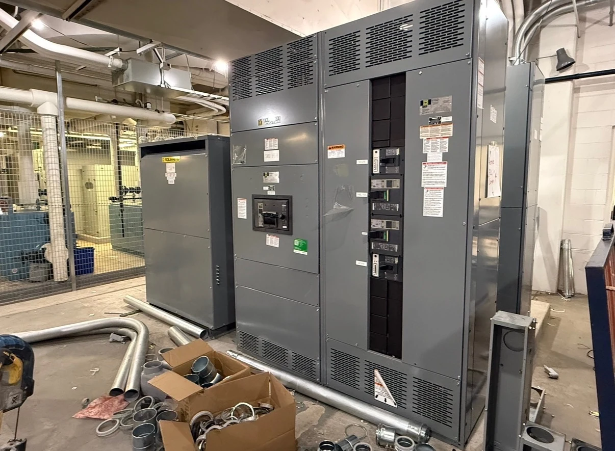
THE MANUFACTURER’S PERSPECTIVE — 02
An automatic transfer switch (ATS) connects a load to a normal or an alternate source, but switching sources does not replace overcurrent protection. For owners, engineers and contractors buying a new power-distribution assembly, the critical question is whether the transfer equipment, protective devices and grounding arrangement work together under the fault conditions and operating states the project can actually encounter.
Start with both source paths
Give the manufacturer a current one-line showing the normal source, alternate source, ATS, upstream protective devices and loads served. Identify the system voltage, phase and wire arrangement, continuous load, conductor routes and any planned expansion. Note whether the alternate source is a generator or another utility supply; its protection characteristics may be quite different.
Have the project engineer establish available fault current at the relevant connection points for each credible source and configuration, including future source changes where known. Utility contribution can be high, while a generator may supply a lower, changing fault current. Both the maximum duty and the minimum current needed for protection to operate deserve review.
Match switch withstand to the clearing device
An ATS withstand and closing rating describes its ability to withstand and close into a fault under specified conditions; it is not the same as the interrupting rating of a circuit breaker. The selected assembly must be evaluated against the available fault current and the protective device that clears that fault, for each applicable source path.
Ask for the applicable rating evidence and conditions for the proposed switch and protective-device combination. A rating may depend on a particular breaker, fuse or specified clearing time. An upstream device with an adequate interrupting rating does not automatically make the transfer switch suitable. Device substitutions can invalidate the assumed combination and require engineering review.
Coordinate protection without assuming selectivity
The coordination study compares protective-device characteristics across the range of currents and operating times expected in the system. The goal is to limit the outage to the affected circuit where the design and applicable requirements call for it. A feeder breaker that clears a fault before an upstream device can preserve power to unrelated loads.
However, settings that improve selectivity may increase fault-clearing time and affect equipment withstand or arc-flash exposure. Generator-source fault current may also fall below a trip threshold that works on utility power. The study provider should evaluate both sources, document limitations and recommend settings; an ATS rating alone is not proof of selective coordination.
Resolve neutral and ground-fault interfaces
Whether the transfer equipment switches the neutral depends on the system grounding design and source configuration, not simply on the number of load conductors. The engineer should identify grounding and bonding locations, whether the alternate source is separately derived, and the required pole arrangement before selecting a switch or preparing the assembly drawings.
Ground-fault sensing and protection must also be coordinated with those choices. An incorrectly defined neutral path can produce unintended sensing or leave protection ineffective. Provide the manufacturer with the grounding diagram and device locations, and have the protection specialist confirm sensing arrangement, settings and any testing requirements for both source states.
Define transfer behavior and controls
An open-transition transfer introduces an interruption between sources; a proposed closed-transition scheme can briefly parallel them and may require additional source, protection and utility review. Identify permitted operating states and any interlocks early. Recalculate fault conditions for configurations the design actually permits rather than assuming sources can never contribute simultaneously.
Document source sensing, generator start signals, time delays, alarms, control-power dependencies and remote monitoring interfaces. A transfer switch does not inherently determine whether a faulted load should be re-energized. Ask the engineer to specify necessary trip-related inhibiting or interlocks and confirm that the selected controls support the intended sequence.
Buy against a documented protection scope
Request a proposal that identifies the transfer equipment, protective devices on each source, ratings and their qualifying conditions, enclosure, terminal arrangements and control interfaces. Clarify what the direct manufacturer supplies in the new assembly versus what the contractor, generator supplier and study provider furnish. If domestic component sourcing is required, identify it and verify availability for each specified item.
Set review milestones for one-line approval, device selection, coordination results and release to manufacture. Ask for drawings, device data, rating documentation, a control sequence and agreed factory test records. Allow time for utility or authority review where applicable and for approved changes. Qualified personnel should perform installation, setting verification and commissioning under site procedures and manufacturer instructions.
LET'S BUILD SOMETHING RELIABLE — 03
Ready to talk
switchgear?
Tell us about the new equipment your project needs. Include as much or as little detail as you have today.
(951) 403-5738CALL TO DISCUSS YOUR PROJECT