
BUILT IN THE USA. READY FOR YOUR PROJECT.
Control Power for Switchgear
A switchgear lineup can distribute power while relying on a separate, smaller supply to operate its controls.
DIRECT FROM THE MANUFACTURER / NEW EQUIPMENT
THE MANUFACTURER’S PERSPECTIVE — 02
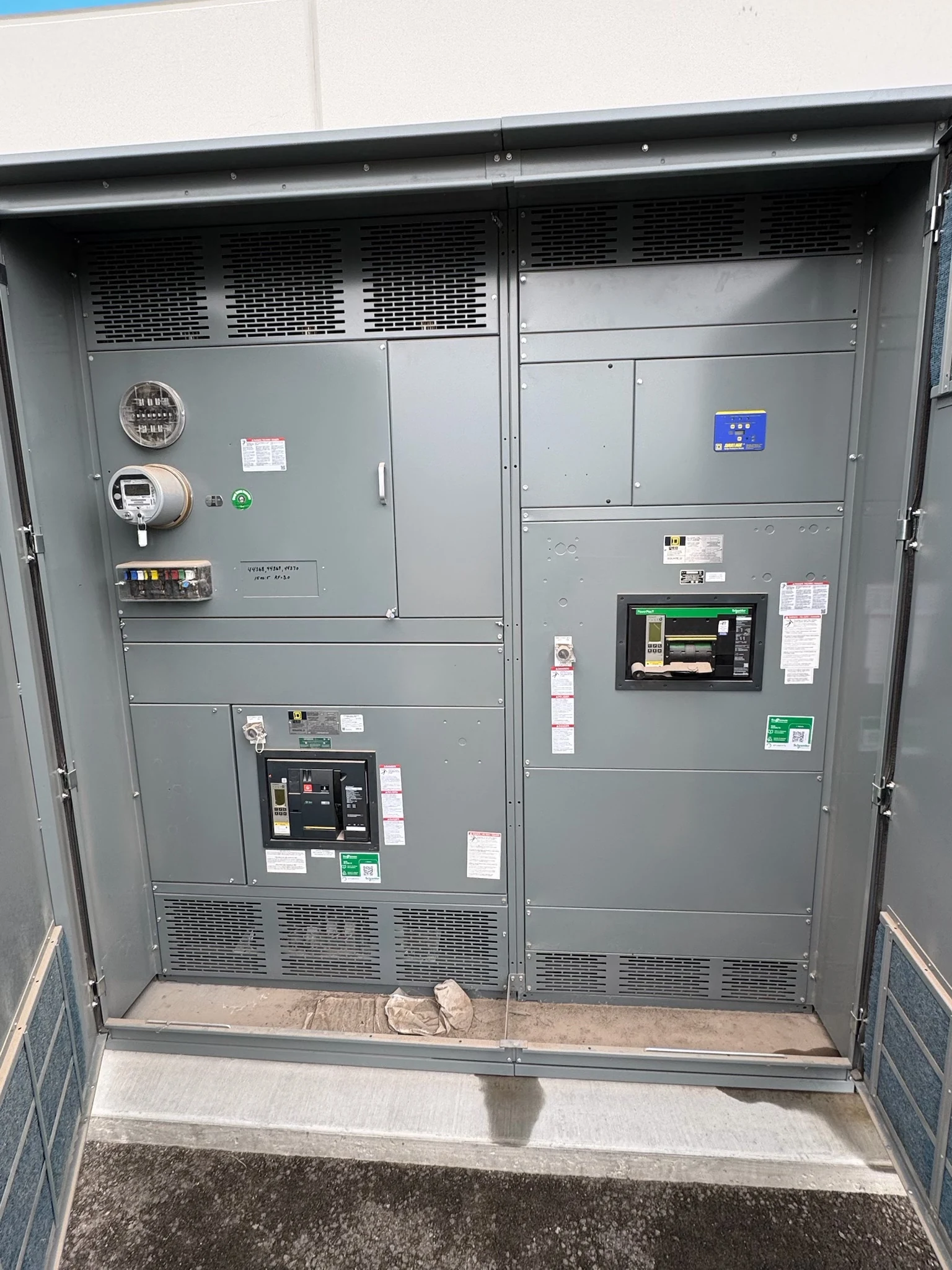
A switchgear lineup can distribute power while relying on a separate, smaller supply to operate its controls. That control supply may support protective relays, breaker coils, indicators, alarms and communications, depending on the design. For engineers, contractors and facility owners, the important question is not simply what voltage to specify, but which functions must remain available when a source or component fails.
Start with the functions that need power
List every control load and its normal, starting and momentary demand. A relay, a closing coil and a communications gateway have different operating patterns; a supply sized from steady consumption alone may not support simultaneous demands or coil inrush. Identify required operating voltage, tolerance, frequency or DC polarity, and any manufacturer limits for each connected device.
Then define which functions matter during an outage. A breaker may need a reliable trip supply even when the main bus is unavailable, while an indicator may be less critical. Describe required local and remote indications, alarm reporting and any trip or close restrictions so the design reflects the facility’s operating philosophy.
Compare transformer and battery-backed sources
A control power transformer can derive an AC supply from an identified source in the distribution system. Its convenience depends on that source remaining energized: if the feeding bus is lost, the transformer alone cannot sustain the controls. Show the transformer connection and account for load, inrush, voltage variation and available fault duty in its selection.
A battery-backed DC system can support selected functions during loss of AC, but requires a defined charger, battery, distribution and monitoring arrangement. The project engineer should establish the required standby interval, load duty cycle and end-of-life assumptions. Battery autonomy, enclosure space, maintenance and replacement responsibilities can materially change the procurement scope.
Protect and isolate each control circuit
Identify the source, disconnecting means and overcurrent protection for each branch, including transformer primary and secondary protection where applicable. Protective devices and wiring must suit their voltage, available fault current and connected equipment. Separating critical trip circuits from less essential loads can limit a single branch fault’s effect, subject to the engineered protection scheme.
Document isolation boundaries for the lineup and any external supply. An independently powered control circuit can remain energized when the main source is absent, creating an important interface and labeling concern. Qualified personnel should apply the site’s electrical safety procedures and manufacturer instructions; a control switch alone is not an assumed isolation point.
Specify wiring and outside connections
Provide a control schematic and terminal plan showing source and return conductors, protective devices, wire identification, grounding where required, and field termination points. Account for voltage drop, conductor suitability, routing and segregation in the design. Note which conductors and terminal blocks are included in the new assembly and which are furnished by the installing contractor.
External interfaces need the same precision: identify contact type, signal voltage and polarity, load or input requirements, and whether a signal is maintained or momentary. For a battery system located outside the lineup, define cable responsibility, disconnect and protection locations, polarity identification and supervision signals. Resolve these boundaries before equipment drawings are approved.
Design for loss and recovery of control power
A source transfer arrangement can improve availability, but it adds logic, components and possible common failure paths. Agree on whether interruption is acceptable, which source has priority and how unintended backfeed is prevented by the engineered design. A second source is not truly independent if it relies on the same vulnerable upstream supply or protection.
Record the expected response to lost voltage, a charger alarm, a failed branch and restoration of supply. Depending on the selected devices and scheme, loss of control power may prevent tripping, closing, indication or communications; do not assume a universal fail-safe position. Assign alarm destinations and decide who reviews the resulting operating states.
Carry decisions through purchase and testing
Send the direct manufacturer the one-line, control-load schedule, source characteristics, required autonomy, logic narrative and field interface list with the quotation request. Ask proposals to distinguish included transformers, batteries, chargers, protection and monitoring from owner-furnished items. Compare drawings, functional test scope, documentation and exceptions as well as the equipment price.
Reserve time for source-data confirmation, drawing review, component procurement and resolution of interface changes; actual schedules depend on project scope and availability. Define factory checks and acceptance criteria for wiring, logic and selected source-failure scenarios, then coordinate field integration and commissioning with qualified personnel. Turnover should include final schematics, settings, test records and operating documentation.
LET'S BUILD SOMETHING RELIABLE — 03
Ready to talk
switchgear?
Tell us about the new equipment your project needs. Include as much or as little detail as you have today.
(951) 403-5738CALL TO DISCUSS YOUR PROJECT