
BUILT IN THE USA. READY FOR YOUR PROJECT.
Electrical Switchboards for Hospitals
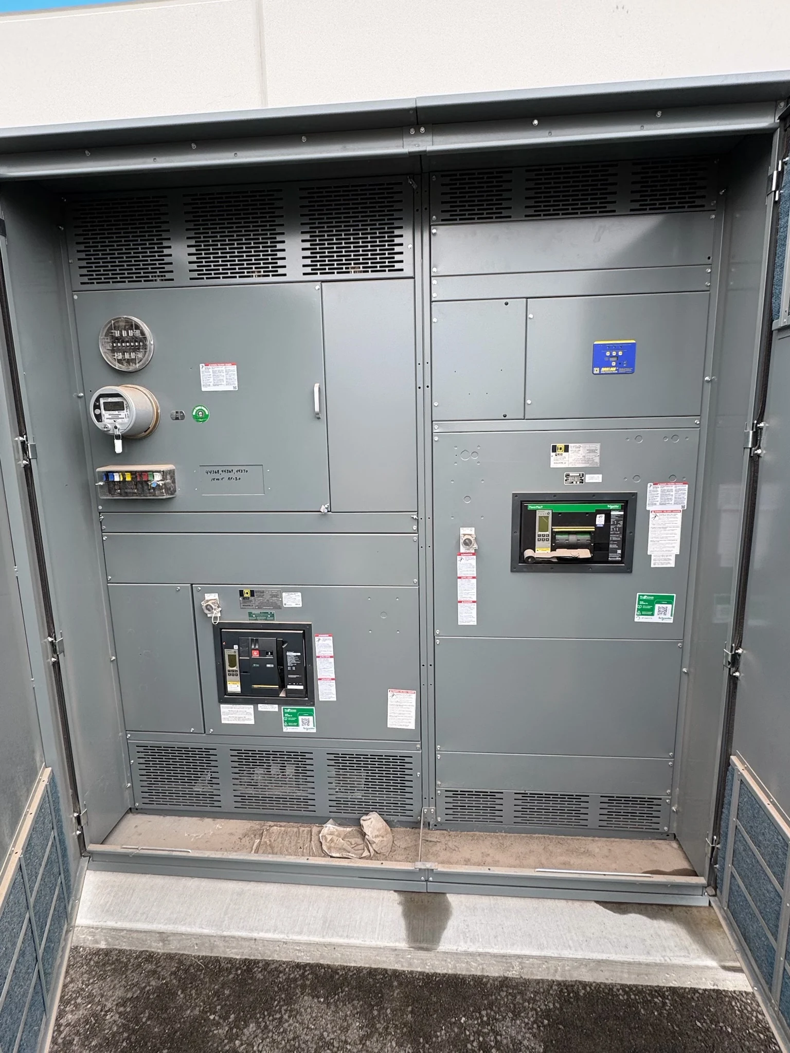
A hospital switchboard distributes low-voltage power to feeders whose destinations may include clinical areas, building systems and transfer equipment.
DIRECT FROM THE MANUFACTURER / NEW EQUIPMENT
THE MANUFACTURER’S PERSPECTIVE — 02
A hospital switchboard distributes low-voltage power to feeders whose destinations may include clinical areas, building systems and transfer equipment. Selecting a new assembly involves more than matching a main rating: a fault or planned outage must not unnecessarily interrupt patient care. Owners and specifiers need a clear picture of sources, essential loads and operating constraints before purchasing equipment.
Map the hospital distribution paths
Start with a current one-line diagram showing the utility service, transformers, generators, switchboards, transfer switches and downstream panels. Identify which feeders serve patient care, life safety and building support functions. Clinical and facilities staff should flag loads that cannot tolerate a transfer interruption, because a switchboard and generator alone do not provide uninterrupted power.
For a Type 1 essential electrical system, the design addresses life safety, critical and equipment branches. Show where normal and alternate supplies enter each transfer switch and where the designated branch distribution begins. The engineer must determine required separation, allowable arrangements and applicable rules; placing critical-sounding loads together does not automatically make a compliant essential system.
Coordinate transfer and alternate power
A switchboard may supply normal or alternate feeders to transfer equipment, or distribute power downstream of it. Identify each boundary on the drawings and specify who supplies the transfer switches, controls, wiring and field connections. Provide source characteristics, feeder loads, starting demands and any generator load-management sequence so the equipment fits the overall operating plan.
Confirm transfer-switch voltage, current and short-circuit capabilities against the engineered system, including both source conditions. The design team should also resolve switched versus solid neutral arrangements and grounding interfaces. For sensitive clinical or information systems, assess separately whether uninterruptible power or another ride-through solution is needed during transfer; do not assume that every load remains continuously energized.
Balance fault protection and continuity
Provide the manufacturer with available fault-current information for the service and alternate-source configurations, along with upstream and downstream protective device data. The engineer evaluates assembly short-circuit rating, device interrupting duty and coordination. A feeder fault should be assessed for its potential to disconnect unrelated care areas as well as for the ability of equipment to withstand the fault.
The protection study should identify where selective coordination is required and examine actual device characteristics across relevant fault levels. Settings, ground-fault protection and clearing times can also affect arc-flash exposure; improving one objective may constrain another. Qualified engineers must resolve these tradeoffs under the adopted codes and document the chosen device types and settings.
Fit the assembly to the electrical room
Supply room dimensions, door and delivery-route restrictions, floor conditions and cable entry preferences. Show conductor quantities and sizes, neutral and grounding connections, plus any transformer or busway interface. The resulting layout needs usable termination and maintenance access, working clearances and ventilation consistent with the approved design and applicable requirements.
A compact lineup can save floor space but may make future feeder additions or access more difficult. Compare spare breaker positions with reserved physical space and bus capacity; an empty section is not proof that every future load can be accommodated. For an occupied hospital, also consider whether the delivery route and construction zone conflict with clinical access or infection-control planning.
Define the quotation and submittals
Send a direct manufacturer the one-line, load schedule, system voltage and phase configuration, fault data, enclosure conditions, feeder schedule and specification. Identify metering, alarm contacts, network interfaces and future capacity needs. Include the applicable utility and authority requirements, and disclose any US-made component sourcing requirements for review rather than assuming every component qualifies.
Request an itemized scope, drawings, device schedules, connection details, exceptions and proposed factory inspection or test records. UL 891 may be relevant to the specified low-voltage switchboard; confirm the exact assembly listing and its scope for the project. Compare proposals on documented ratings, included devices and interfaces, not simply the dimensions or initial price.
Schedule around patient care and commissioning
For a replacement project, identify affected circuits and verify dependencies with hospital operations, clinical leadership, the contractor and the design team. The owner should coordinate permitted outage windows, patient-care contingencies, any temporary power design and a rollback plan. Site conditions and approvals can change the sequence, so align equipment delivery and submittal reviews with that plan.
Agree who performs installation, field testing, protective settings, transfer-function checks and final energization authorization. Qualified personnel must follow site safety procedures, applicable codes and equipment instructions. At turnover, request final drawings, test results, approved settings, manuals and feeder identification so the facility can maintain a reliable record of the new distribution arrangement.
LET'S BUILD SOMETHING RELIABLE — 03
Ready to talk
switchgear?
Tell us about the new equipment your project needs. Include as much or as little detail as you have today.
(951) 403-5738CALL TO DISCUSS YOUR PROJECT